Sheet feeder and printer

a feeder and printer technology, applied in the field of paper feeders and printers, can solve the problems of increasing the size of the paper feeding apparatus, unable to transmit the paper feeding force to the sheets, and sheets becoming wrinkled, etc., and achieves the effects of low rigidity, easy paper jams, and high rigidity of sheets

Inactive Publication Date: 2005-06-30
F&F
View PDF2 Cites 14 Cited by
  • Summary
  • Abstract
  • Description
  • Claims
  • Application Information

AI Technical Summary

Benefits of technology

[0013] In the present invention, conversely by using the flexibility of the drive shaft and using elastic bodies, such as a plurality of springs, that move independently, short parts of the drive shaft, as represented by the roller parts, are set as units, and the respective roller parts are pressed in the direction of the base plate substantially independently. With this construction, the respective roller parts tightly contact the sheets independently, so that by using a pickup roller that uses a flexible drive shaft instead of a pickup roller that uses a highly rigid drive shaft, the contact area between the roller parts and the sheets and the contact length in the sheet width direction can be increased. Accordingly, by using a flexible pickup roller, it is possible to transmit a paper feeding force to the sheets more effectively, which increases the reliability of paper feeding and can eradicate problems such as skewing and wrinkling of the sheets.
[0034] If the sheets have high rigidity (stiffness), as described above, it is possible to make the distance between the separation wall and the parts contacted by the pickup roller longer, so that the difference between when there are many remaining sheets in the sheet tray and when there are few remaining sheets can be reduced. The difference in resistance when the front ends of sheets strike the separation wall is also large, so that multiple feeding is easier to avoid. In addition, since a balanced force is provided to sheets when feeding the sheets, there is no bending or skewing and it is also difficult for paper jams to occur. Since the sheets are bent in the sheet width direction, the rigidity can be increased even for thin sheets. However, by bending the sheets, the contact area between the sheets and the pickup roller falls, so that the driving force cannot be effectively transmitted to sheets. As a result, there is the problem that it is not possible to feed sheets with high reliability. However, with the paper feeding apparatus of the present invention, since the pickup roller is flexible, the pickup roller also bends so as to substantially assume the bent shape of the sheets and it becomes possible to make the pickup roller contact sheets with a uniform pressure in the sheet width direction, even for bent sheets. By doing so, it is possible to apply an approximately uniform paper feeding force in the paper feeding direction to sheets in a state where the sheets are made effectively rigid or stiff by bending the sheets. Accordingly, it is possible to provide a paper feeding apparatus that has even higher reliability in spite of being a slim paper feeding apparatus.

Problems solved by technology

The ability to set cut sheets easily is also important, and if a complex mechanism is required for moving a pickup roller to set sheets, this can also cause increases in the size of the paper feeding apparatus.
However, if the drive shaft flexibly deforms, even if both ends of the drive shaft are pressed, it will not be possible to apply a predetermined force onto the sheets with roller parts along the length of the pickup roller, that is, in the sheet width direction, so that it will not be possible to transmit the paper feeding force to the sheets.
Alternatively, the paper feeding force is transmitted to the sheets in an extremely unbalanced state, so that the sheets become wrinkled and it becomes no longer possible to feed sheets in a straight manner.
This problem simply worsens if the force applied to the shaft is increased, and if the rigidity is increased by whatever method to eradicate this problem, a rigid member with an increased cross-sectional area inevitably has to be used, so that the thickness of the paper feeding apparatus is increased.

Method used


Image

  • Sheet feeder and printer
  • Sheet feeder and printer
  • Sheet feeder and printer

Examples


Embodiment Construction

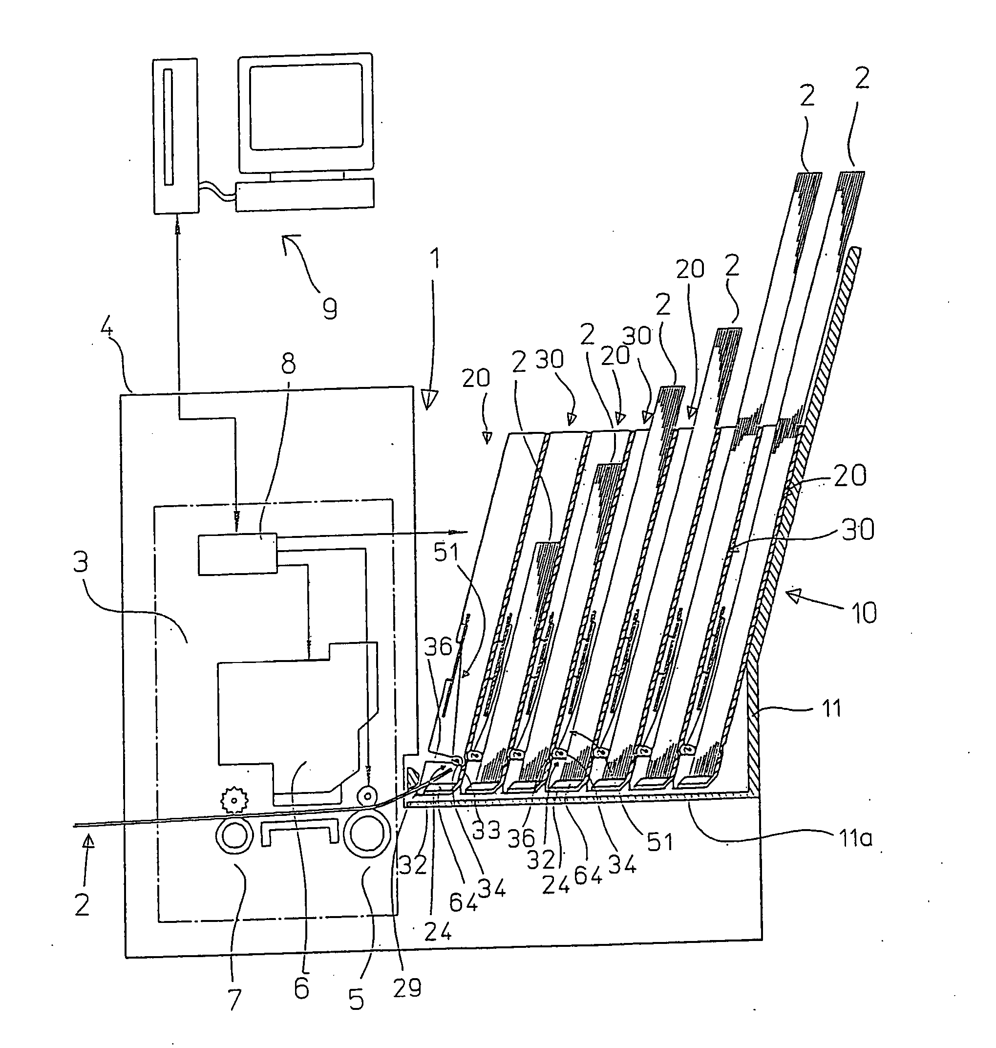
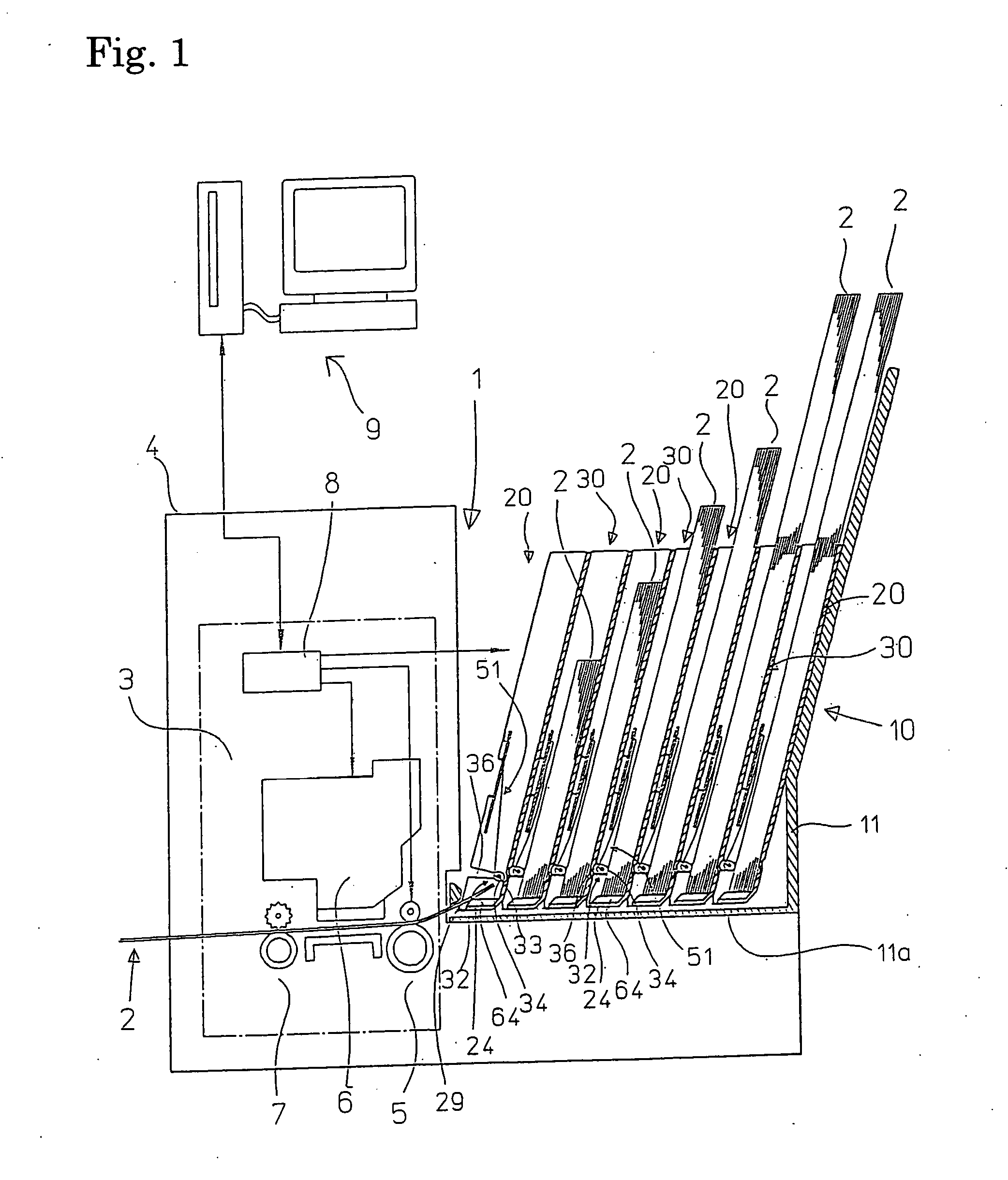
[0053] The present invention is described in more detail below with reference to the attached drawings. FIG. 1 schematically shows a printer with a multiple paper feeding apparatus, that is, a multitray including paper feeding apparatuses according to the present invention. The printer 1 includes a multitray 10 in which two types of paper feeding apparatuses 20 and 30 are alternately stacked on seven levels, with the respective paper feeding apparatuses 20 and 30 being capable of storing a plurality of sheet like papers (sheets), that is, cut sheets 2. The printer 1 also has a printing unit 3 that prints on the cut sheets 2 supplied from the multitray 10. The printing unit 3 includes a paper feeder 5, an ink jet-type printing head 6, and a discharge feeder 7. The printing unit 3 also includes a control unit 8 that receives print data and commands from a computer 9 that is a host, and controls the printing head 6, the feeders 5 and 7, and the multitray 10 based on the received inform...


PUM


Abstract

A paper feeding apparatus according to the present invention has a pickup roller, which includes a drive shaft disposed so as to cross a sheet tray and a plurality of roller parts intermittently attached to the drive shaft, and elastic supporting means, which substantially independently supports a plurality of exposed parts of the drive shaft so as to apply pressure towards a base plate of the sheet tray. In the paper feeding apparatus, respective exposed parts of the drive shaft, which has a narrow diameter and being flexible, are independently pressurized towards the sheet tray of the base plate, so that the respective roller parts contact tightly with the sheets substantially independently. Accordingly, sheets can be fed with high reliability by making the most of the flexibility of the drive shaft. The extremely slim and highly reliable paper feeding apparatus with the extremely slim pickup roller is provided. By stacking a plurality of these paper feeding apparatuses, a compact multitray can be provided.

Description

TECHNICAL FIELD [0001] The present invention relates to a paper feeding apparatus that can store a plurality of sheets and can feed the stored sheets one at a time, and to a multiple paper feeding apparatus in which paper feeding apparatuses are stacked on a plurality of levels. RELATED ART [0002] Among copiers and large-scale printers, there are devices in which a plurality of sheet trays or paper feeding apparatuses are stacked so that it is possible to freely select and print on sheets (that is cut paper or cut sheets) of different sizes and types. In such copiers and printers, sheets of different types and / or sizes are stored in advance in the paper feeding apparatuses, so that when the cut sheets to be printed upon are changed, it is possible to change the size and / or type of printed sheet easily by merely selecting the paper feeding apparatus storing the intended cut sheets as the paper feeding tray to be used. [0003] To make it possible to select and supply a plurality of typ...

Claims


Application Information

Patent Timeline
Patent Type & Authority Applications(United States)
IPC IPC(8): B65H3/06B65H27/00
CPCB65H3/06B65H3/0638B65H2511/17B65H2511/12B65H2404/1371B65H2404/137B65H2404/1341B65H2404/133B65H3/0661B65H3/0676B65H27/00B65H2403/72B65H2404/1321B65H2220/01B65H2220/04B65H2220/02B65H2220/11
Inventor FUJIWARA, HITOSHI
Owner F&F
Why Eureka
Try Eureka