Oscillating disc cutter with speed controlling bearings

Inactive Publication Date: 2005-06-30
ODYSSEY TECH
View PDF27 Cites 2 Cited by
  • Summary
  • Abstract
  • Description
  • Claims
  • Application Information

AI Technical Summary

Benefits of technology

[0009] Accordingly the present invention provides an oscillating disc cutter including a cutting disc and a drive mechanism, the drive mechanism including a drive shaft to effect eccentric oscillation of the cutting disc and a radial bearing disposed to permit relative rotation between the drive shaft and the cutting disc, the cutter further including a first axial bearing disposed to react axial forces while accommodating induced rotation of the cutting disc when operatively engaged and to induce a rotational drag thereby limiting rotational speed of the cutting disc when free running.
[0013] Preferably, pressure in the fluid bearing is maintained at a level such that a predetermined maximum running clearance in the hydrostatic bearing is maintained thereby inducing shear forces in the oil of the hydrostatic bearing. Preferably, the shear forces cause rotational drag in the bearing thereby limiting the rotational speed of the cutting disc in when free running.

Problems solved by technology

Thus can cause significant wear and damage to the cutting edge.
Such a gear arrangement is heavy, prone to wear, maintenance issues, and causes additional drag when the cutter is engaged with the rock face.

Method used


Image

  • Oscillating disc cutter with speed controlling bearings
  • Oscillating disc cutter with speed controlling bearings
  • Oscillating disc cutter with speed controlling bearings

Examples


Embodiment Construction

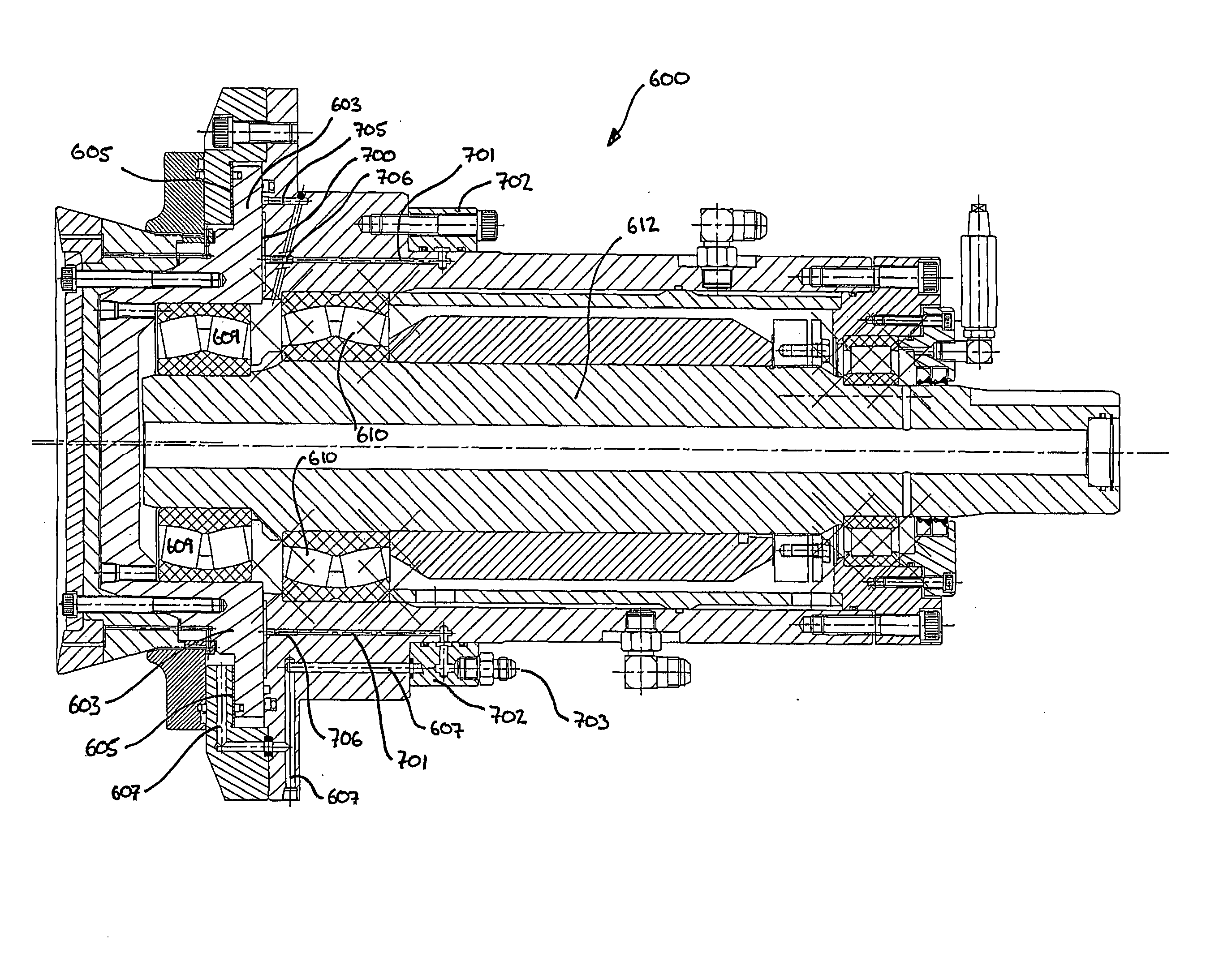
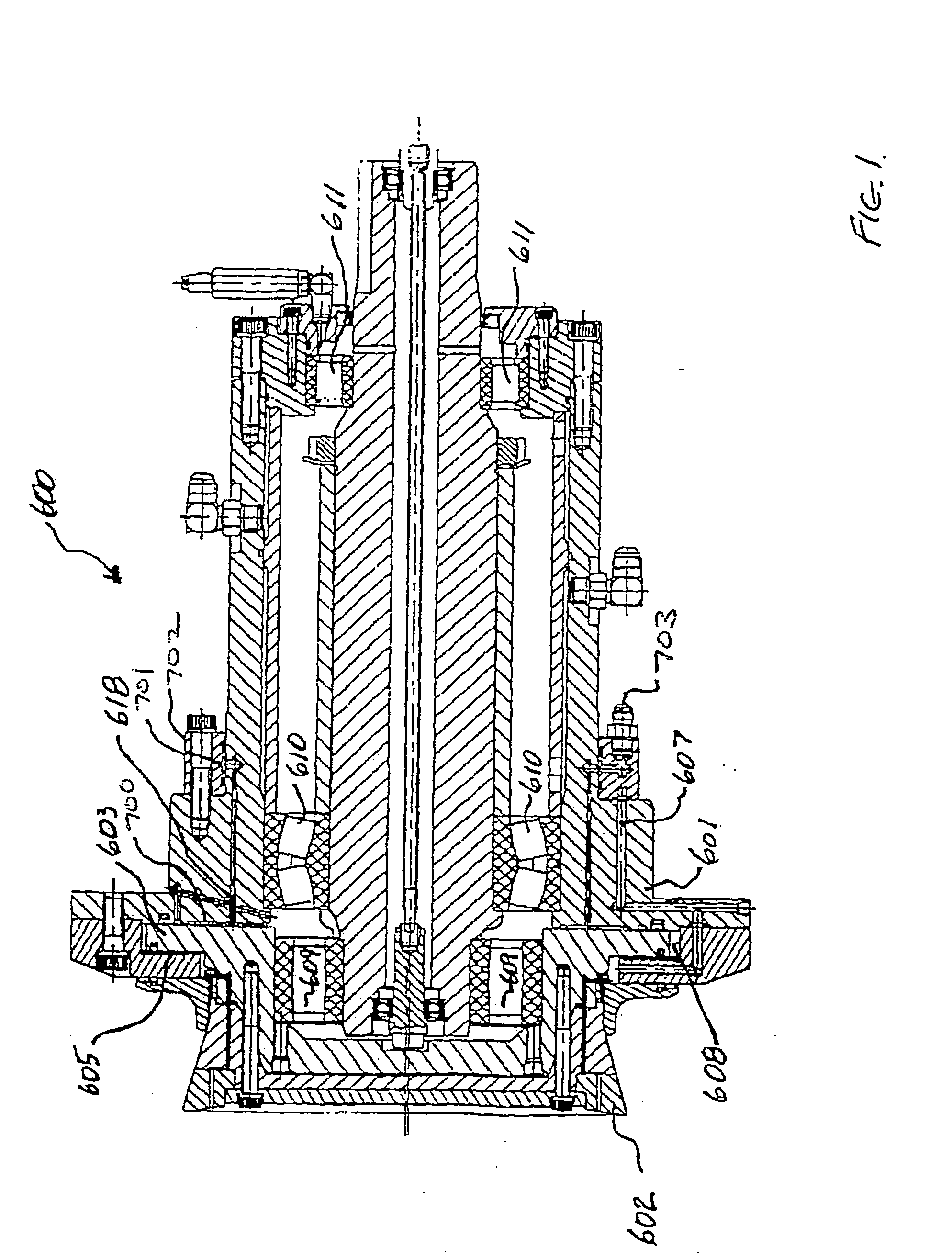
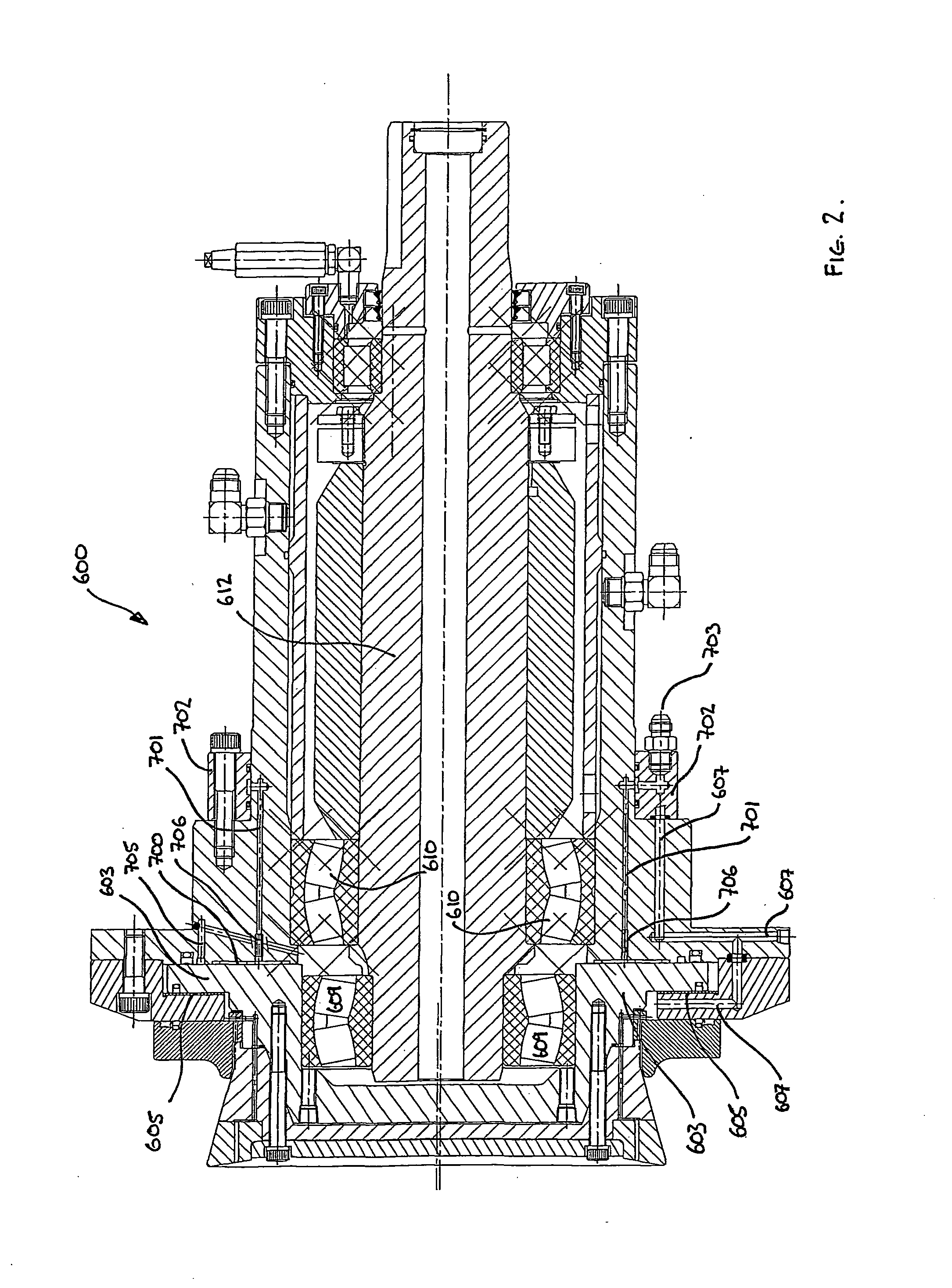
[0021] The oscillating disc cutter shown in the accompanying drawing is generally similar in configuration to that shown in FIG. 7 of international patent specification PCT / AU00 / 00066, with like numbers referring to the components in that drawing as described in the description of the international patent specification.

[0022] Instead of the bearings 605 and 606 from PCT / AU00 / 00066 being water lubricated, only bearing 605 in the present invention is water lubricated. Bearing 606 is replaced by a hydrostatic bearing 700 supplied with high pressure oil through an annular passageway 701 inside a demountable ring 702, to which oil is supplied under pressure via nipple 703. The bearing 700 contains pockets 800 in the normal manner of hydrostatic bearings.

[0023] As can clearly be seen in FIG. 3A, these pockets may be in the form of a concentric grid pattern on the casing body opposing the disc 603, however, in alternative embodiments they may take on any form as is known in the art of hy...


PUM


Abstract

An oscillating disc cutter including a cutting disc and a drive mechanism. The drive mechanism includes a drive shaft to effect eccentric oscillation of the cutting disc and a radial bearing disposed to permit relative rotation between the drive shaft and the cutting disc. The cutter further including a hydrostatic axial bearing disposed to react axial forces while accommodating induced rotation of the cutting disc when operatively engaged and to induce a rotational drag thereby limiting rotational peed of the cutting disc when free running. A water pressurized fluid bearing induces a predetermined axial load in the hydrostatic bearing such that a predetermined maximum running clearance in the hydrostatic bearing is maintained.

Description

FIELD OF THE INVENTION [0001] This invention relates to an oscillating disc cutter with speed controlling bearings and has been devised particularly though not solely to prevent high speed rotation of a disc cutter when the cutting disc is disengaged from a rock face. BACKGROUND OF THE INVENTION [0002] Oscillating disc cutters of the type described in international patent specification PCT / AU00 / 00066 (the contents of which are incorporated herein by way of cross reference) have the general requirement that a mechanism is provided to prevent the cutting disc from rotating at a high speed when the cutter is not engaging the rock face. [0003] It should be noted that the reference to international patent specification PCT / AU00 / 00066 is not an admission that this publication forms part of the common general knowledge in Australia or in any other territory. [0004] In normal cutting mode, when the disc cutter is presented to the cutting face the disc naturally rotates at about 30-40 rpm in...

Claims


Application Information

Patent Timeline
IPC IPC(8): E21C25/16E21C27/12E21C27/24E21D9/10
CPCE21C25/16F16C32/0692F16C21/00E21D9/1046
Inventor SUGDEN, DAVID BURNET
Owner ODYSSEY TECH
Why Eureka
Try Eureka