Vertical axis wind turbine device

a wind turbine and vertical axis technology, applied in vessel construction, renewable energy generation, greenhouse gas reduction, etc., can solve the problems of unstable starting characteristics and delay in the practical use of that technology, and achieve the effect of reducing drag, preventing the reduction of rotor performance and noise generation, and reducing wind turbulen

Inactive Publication Date: 2012-02-16
UENO YASUO
View PDF5 Cites 2 Cited by
  • Summary
  • Abstract
  • Description
  • Claims
  • Application Information

AI Technical Summary

Benefits of technology

[0011]The 1st effect of this invention is that by installing a guide vane which section is like a wing section shape on a rotation axis freely for rotation, possible to reduce turbulence of wind caused by the rotation axis, prevent reduction of rotor performance and generation of noise.
[0012]The 2nd effect of this invention is the guide vane stream to wind direction—so-called vane effect, and when wind turbine is stopped in a condition of strong wind, it enables to reduce drag minimum by fixing the direction of the chord parallel to wind direction and reduce wind noise minimum.
[0013]The 3rd effect of this invention is that it prevents noise—so-called wind noise, generated at the trailing edge of the rotor, and prevents resonance of the rotor by turbulence of air flow.
[0014]The 4th effect of this invention is that to be possible to avoid a excessive wind pressure which add to all devices including a pole-like support by pulling down base of the wind turbine to the bottom of the pole-like support where wind velocity is relatively low, and prevent damage or failure, and prevent noise generated by wind beating all the wind turbine devices that travel long distance.
[0015]The 5th effect of this invention is to obtain safe revolution control in a condition of strong wind is blowing by achieving extremely effective braking ability by a plate member which is possible to open and close near by the slat for starting performance, and by this restrict excessive the rotation speed, and it is possible to prevent noise generated under the above condition.

Problems solved by technology

However, practical use of that has been delayed by unstable starting characteristics.

Method used


Image

  • Vertical axis wind turbine device
  • Vertical axis wind turbine device
  • Vertical axis wind turbine device

Examples


embodiment 1

[0026]The 1st embodiment of this invention in the following figures is explained as follows.

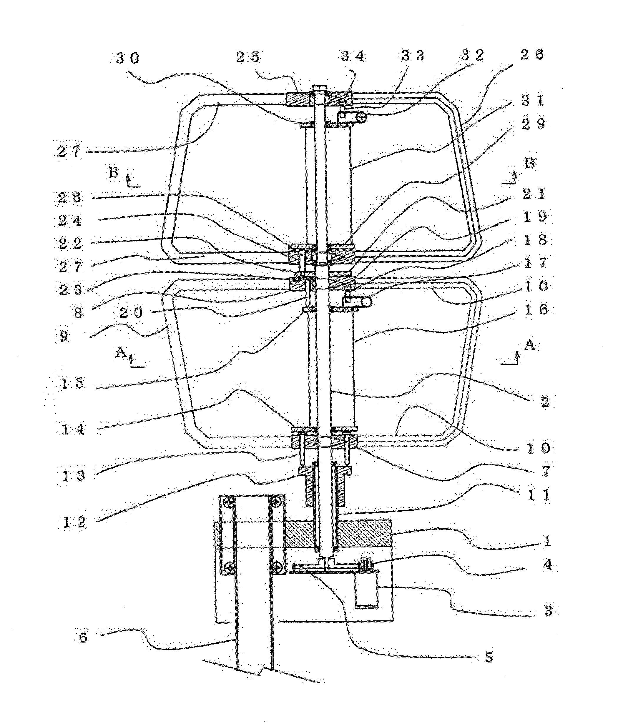
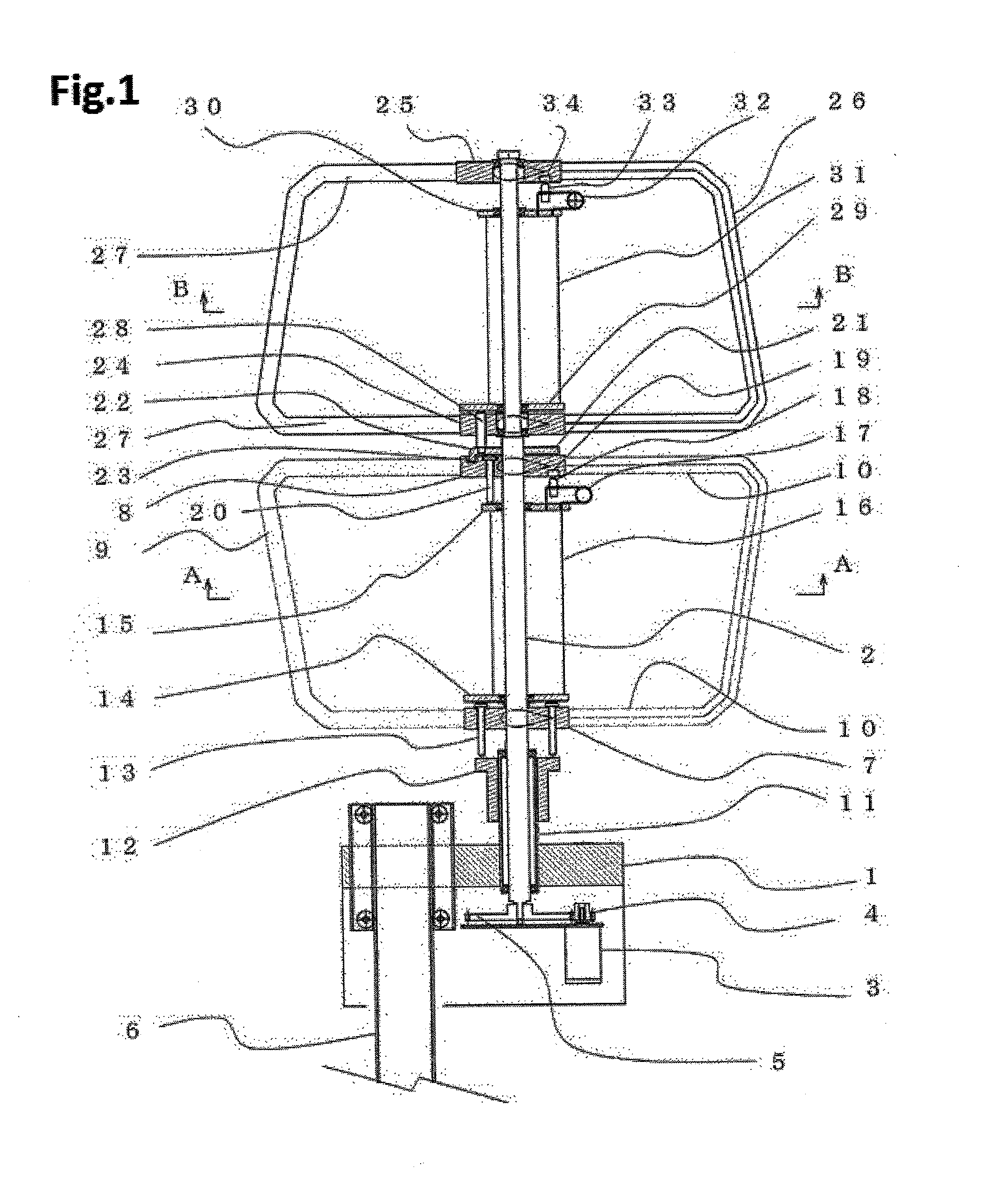
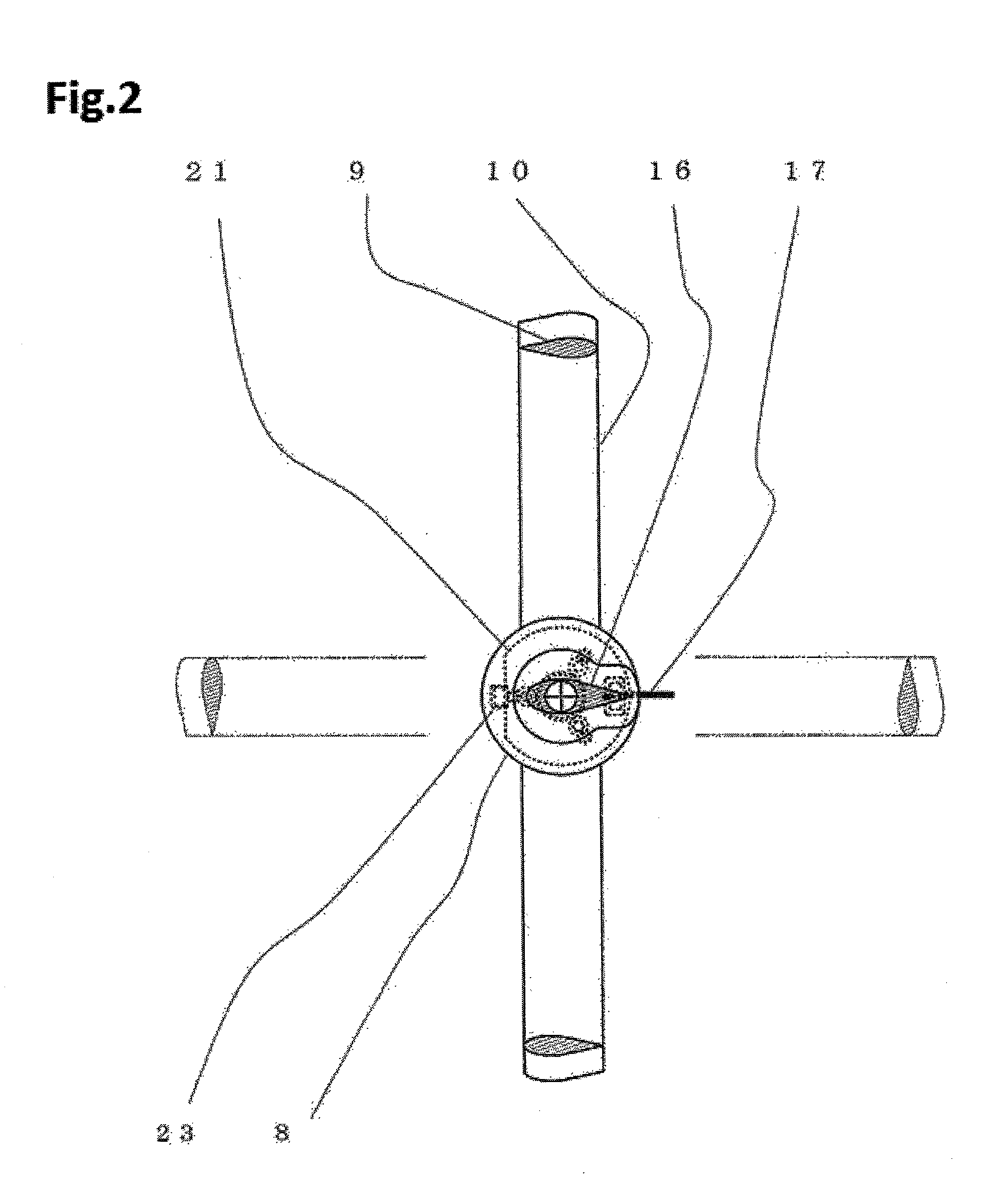
[0027]FIG. 1 is the side section view of the 1st practiced embodiment of this invention, FIG. 2 is the A-A section view of this invention and FIG. 3 is the B-B section view of this invention.

[0028]In FIG. 1, a base 1 support a rotation axis 2 freely for rotation which is vertical to horizon, a electric generator 3 is fixed to the base 1, and the rotation axis 2 is engaged with the electric generator 3 through speed up gears 4, 5 which are arranged at the bottom of the rotation axis 2. 2 hubs 7, 8 are fixed to the rotation axis 2, and 2 rotors 9 and support arms 10 are fixed tightly in substantially “U shape” condition. And on outside diameter of a support pipe 11 of the rotation axis 2, a flange member 12 is arranged freely for sliding upward and downward, and 1st Pin 13 which a penetrate hub 7 contact upper surface of the flange member 12.

[0029]Between the hub 7 and 8, a guide vane member 16...

embodiment 2

[0039]FIG. 4 is the Side Section View of the 2nd embodiment of this invention. Indication of symmetrical part is abbreviated.

[0040]In FIG. 4, a rotation axis 42 which is vertical to horizon is supported by a base 41 freely for rotation, and a electric generator 43 is fixed to the base 41, and connected to the rotation axis 42 through a speed up gears 44, 45 which are lower end of the rotation axis 43. And it is preferable that the base 41 is supported by a pole-like support 46 freely for sliding upward and downward if necessary, however as it is not related to the theme of this invention, detail explanation is abbreviated. 2 hubs 47, 48 are fixed to the rotation axis 42, and 2 rotors 49 and a support arms 50 are fixed to the rotation axis 42 in substantially “U shape” condition.

[0041]And, on outer diameter of the support pipe 51 of the rotation axis 42, a flange 52, which is arranged freely to slide upward and downward, and the 1st pin 53 touch upper surface of the flange 52 through...

embodiment 3

[0047]Structure of the 3rd means of this invention is to provide a wind turbine device which equip with a trailing edge fin made of elastic and soft material on the trailing edge of the rotor which section is similar to wing of aircraft. A rotor itself is same as conventional structure, but a fixing point of the trailing edge fin does not form sharp edge. An elastic trailing fin installed on the trailing edge is formed of soft synthetic rubber, and fitted in a rotor and fixed by known technology as adhesion. A hollow structure is acceptable to increase flexibility.

[0048]The 3rd embodiment of above invention in the figure is explained as follows.

[0049]FIG. 5 is the section drawing which shows structure of 3rd embodiment of this invention.

[0050]In FIG. 5, 101 is the section of the rotor of wind turbine of this invention, which is similar to wing section of aircraft and made of hard plastics or metal, and a flexible and soft trailing fin 102 is arranged on the trailing edge of it. A gr...


PUM


Abstract

This invention provides a vertical axis wind turbine for utilization of wind power for electric generator and mechanical power source which enables big reduction of noise, by supporting a guide vane which section are wing section of aircraft shape to a rotation axis freely for rotation to reduce noise especially when in a condition of strong wind is blowing, by arranging a fixing mechanism to fix the guide vane, and rotors when they become parallel to each other, by adding mechanism to pull down all the wind turbine devices to bottom of a pole-like support, by arranging silencer mechanism composed of flexible member at trailing edge.

Description

TECHNICAL FIELD[0001]This invention relates to countermeasure against noise of a wind turbine device used for a wind power electric generator device, a mechanical power source, etc, especially relates to a vertical axis wind turbine which the rotation axis is in vertical direction and can rotate unrelated to direction of wind.BACKGROUND ART[0002]So far, many improvements have been progressed for above wind turbine device which merits is that it is not affected by direction of wind. However, practical use of that has been delayed by unstable starting characteristics.[0003]However a following patent application by this patent applicant improved starting characteristics and practical use of that has progressed considerably. This wind turbine device of the patent application consists of structure which constant section and plural rotary wings of substantially formed into a U shape which is falling sidelong (hereinafter “U shape”) are fixed to a rotation axis which is supported on a base...

Claims


Application Information

Patent Timeline
Patent Type & Authority Applications(United States)
IPC IPC(8): F03D1/02
CPCF03D3/062F05B2240/915F05B2260/901F05B2260/96Y02E10/728F03D3/02F03D3/04F03D13/20F03D15/10F03D9/25Y02E10/74
Inventor UENO, YASUO
Owner UENO YASUO
Why Eureka
Try Eureka