Manual transmission

a transmission and manual technology, applied in the field of manual transmission, can solve the problems of unavoidable generation of shock, unpleasant feeling for the vehicle driver, and the change in acceleration in the front-rear direction of the vehicle, and achieve the effects of increasing the amplitude factor of the motor drive torque, reducing the size of the effect of the drive torque and large driving torqu

Inactive Publication Date: 2014-03-27
AISIN AI CO LTD
View PDF3 Cites 3 Cited by
  • Summary
  • Abstract
  • Description
  • Claims
  • Application Information

AI Technical Summary

Benefits of technology

[0016]By virtue of this configuration, when a gear stage for low speed travel is selected, the “motor speed reduction ratio” is set to a larger value, whereby the amplification factor of the motor drive torque is increased. Therefore, a large drive torque based on the motor drive torque can be obtained when the vehicle travels at a relatively low speed. As a result, the electric motor can be made smaller in size. On the other hand, when a gear stage for high speed travel is selected, the “motor speed reduction ratio” is set to a smaller value, whereby the rotational speed of the electric motor relative to the vehicle speed can be decreased. Accordingly, the rotational speed of the motor can be restricted to a range in which the energy efficiency is high when the vehicle travels at a relatively higher speed. As a result, a high energy efficiency can be maintained when the vehicle travels at a relatively higher speed.

Problems solved by technology

Accordingly, a shock (a change in acceleration in the front-rear direction of the vehicle) is unavoidably generated as a result of the change in the motor speed reduction ratio.
Generation of such a shock provides unpleasant feel to the vehicle driver.

Method used


Image

  • Manual transmission
  • Manual transmission
  • Manual transmission

Examples


Embodiment Construction

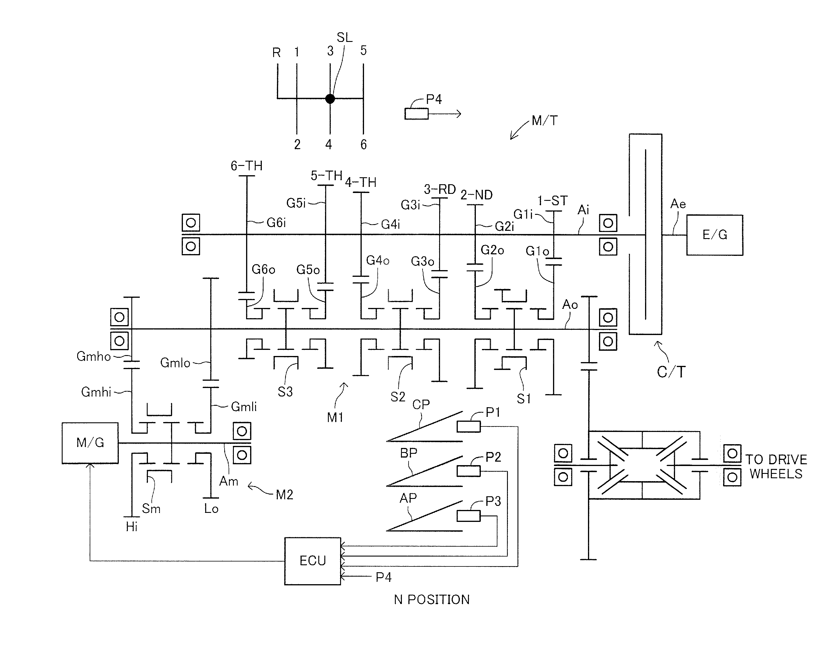
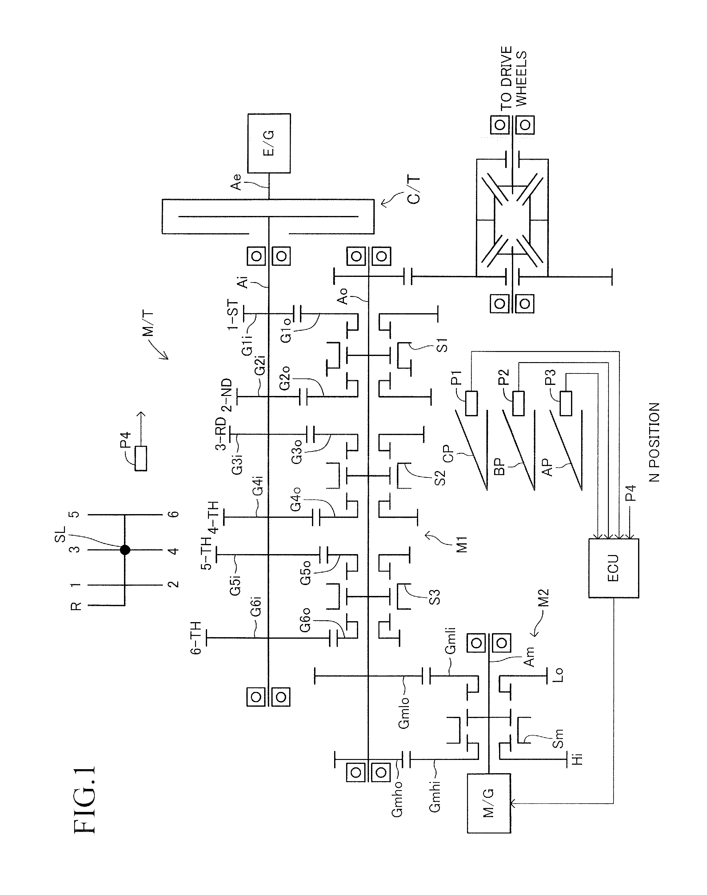
[0036]An example of a power transmission control apparatus (hereinafter referred to as “present apparatus”) of a vehicle which includes a manual transmission M / T according to an embodiment of the present invention will now be described with reference to the drawings. As shown in FIG. 1, the present apparatus is applied to “a vehicle which includes an engine E / G and a motor generator M / G as power sources, and also includes a manual transmission M / T having no torque converter, and a friction clutch C / T”; i.e., the above-described “HV-MT vehicle.” This “HV-MT vehicle” may be a front-wheel-drive vehicle, a rear-wheel-drive vehicle, or a four-wheel-drive vehicle.

(Overall Structure)

[0037]First, the overall structure of the present apparatus will be described. The engine E / G is a well known internal combustion engine, such as a gasoline engine which uses gasoline as fuel, or a diesel engine which uses light oil as fuel.

[0038]The manual transmission M / T is a transmission which does not incl...


PUM


Abstract

This manual transmission includes an input shaft, an output shaft, and an MG shaft. This transmission includes a motor speed change mechanism which establishes a power transmission system between the output shaft and the MG shaft and can selectively set the ratio of rotational speed of the MG shaft to that of the output shaft to one of two values (Hi or Lo). During a period during which a selection operation, which is an operation in the left-right direction of a vehicle of a shift lever, is performed on a shift pattern, the motor speed change mechanism changes the motor speed reduction ratio in a manner interlocked with the selection operation. As a result, during the selection operation, which is a state in which a driver is unlikely to perceive an external shock, the driver receives a shock produced as a result of changing of the motor speed reduction ratio.

Description

TECHNICAL FIELD[0001]The present invention relates to a manual transmission applied to a vehicle which has an internal combustion engine and an electric motor as power sources, and more particularly to a manual transmission applied to a vehicle which includes a friction clutch disposed between the output shaft of the internal combustion engine and the input shaft of the manual transmission.BACKGROUND ART[0002]Conventionally, there has been widely known a so-called hybrid vehicle which includes an engine and an electric motor as power sources (see, for example, Japanese Patent Application Laid-Open (kokai) No. 2000-224710). In such a hybrid vehicle, a structure can be adopted in which the output shaft of the electric motor is connected to one of the output shaft of the internal combustion engine, the input shaft of a transmission, and the output shaft of the transmission. In the following description, drive torque from the output shaft of the internal combustion engine will be referr...

Claims


Application Information

Patent Timeline
Patent Type & Authority Applications(United States)
IPC IPC(8): B60K6/547
CPCY10S903/902B60K6/547B60K6/48B60K2006/4808B60K2006/4841B60W20/00B60W2540/12B60W2540/14B60W2540/16B60Y2400/71B60Y2200/92F16H2200/0021F16H2200/0034F16H61/0437F16H63/22F16H2063/3086F16H2063/208Y10T74/19051Y02T10/62B60W30/19B60W20/30B60W10/10
Inventor OSUKA, SHINYAMASUI, YUKI
Owner AISIN AI CO LTD
Why Eureka
Try Eureka