Heat dissipating device incorporating heat pipe

Inactive Publication Date: 2005-06-30
HON HAI PRECISION IND CO LTD
View PDF8 Cites 41 Cited by
  • Summary
  • Abstract
  • Description
  • Claims
  • Application Information

AI Technical Summary

Benefits of technology

[0008] Accordingly, an object of the present invention is to provide a heat dissipating device inc

Problems solved by technology

Such heat can adversely affect the operational stability of computers.
Thus, the heat sink has a disadvantage that the heat cannot be quickly transferred to the top of the heat sink, thereby reducing heat diss

Method used


Image

  • Heat dissipating device incorporating heat pipe
  • Heat dissipating device incorporating heat pipe
  • Heat dissipating device incorporating heat pipe

Examples


Embodiment Construction

[0018] Reference will now be made to the drawing figures to describe the present invention in detail.

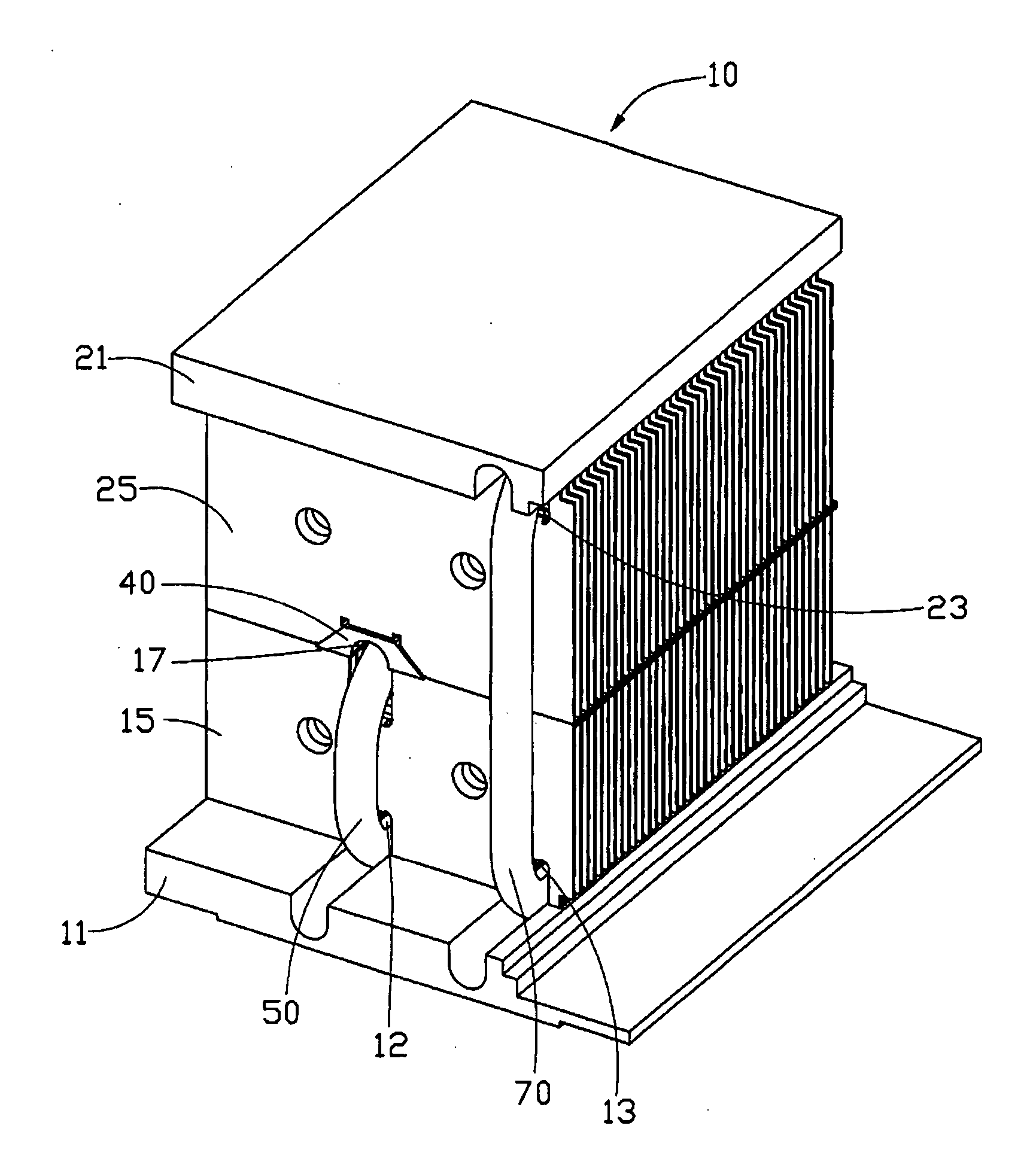
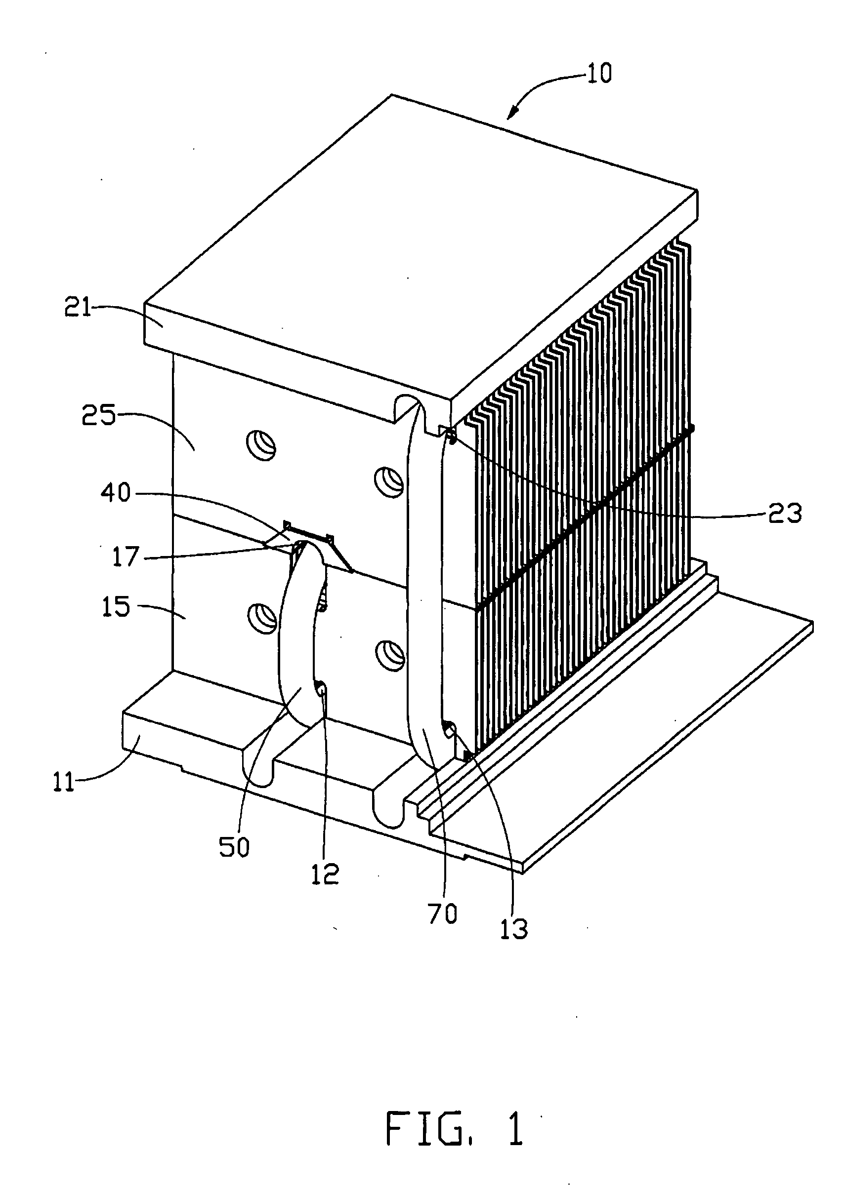
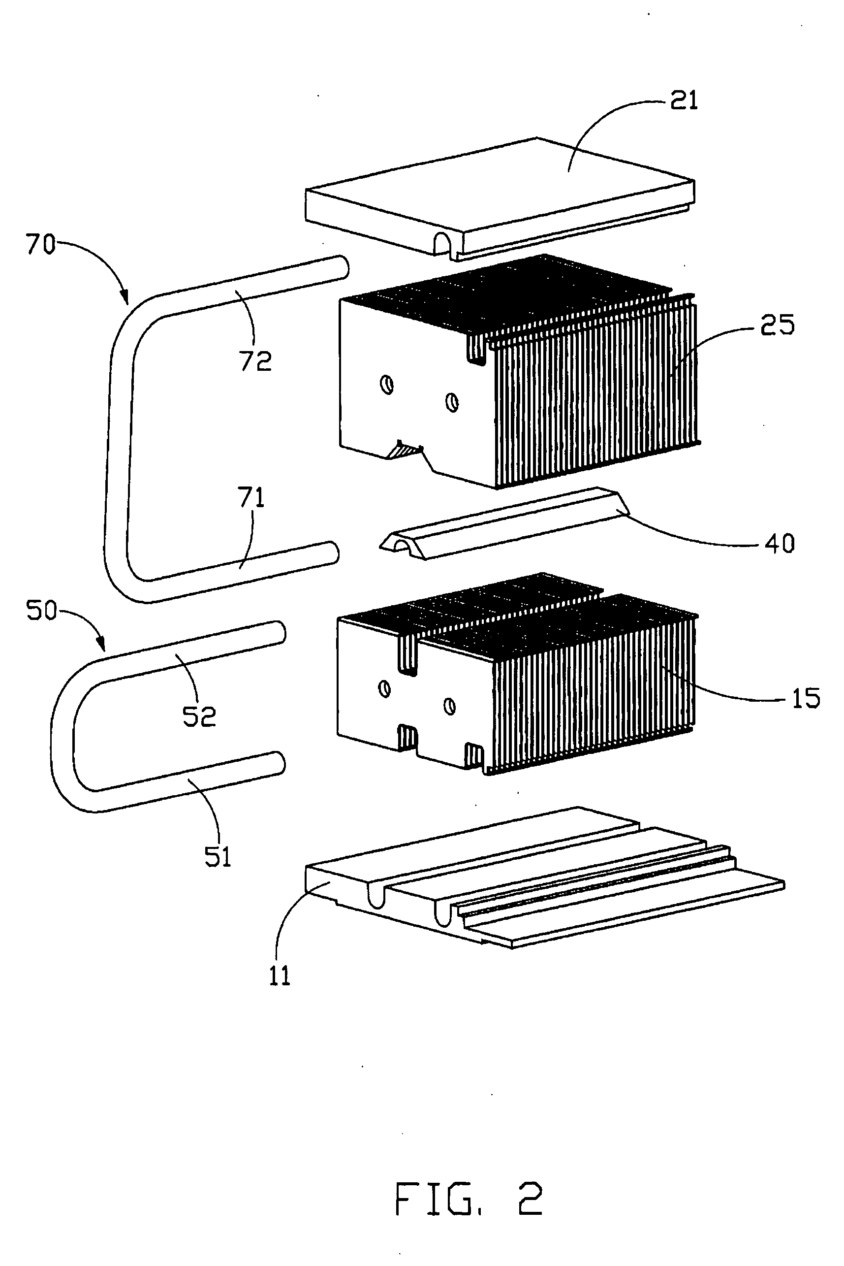
[0019]FIG. 1 to FIG. 4 show a heat dissipating device in accordance with the preferred embodiment of the present invention, for removing heat from computer electronic devices such as CPUs (not shown). The heat dissipating device comprises a heat sink 10, a first heat pipe 50 and a second heat pipe 70.

[0020] The heat sink 10 has a first base 11, a second base 21 and a plurality of spaced fins disposed between the two bases 11, 12. The fins include a first fin unit 15 and a second fin unit 25 disposed on the first fin unit 15. The first base 11 has a top surface and a bottom surface opposite to the top surface. The bottom surface of the first base 11 is for contacting with the CPU for heat-absorption. A pair of parallel grooves is defined in the top surface of the first base 11, and correspondingly, the first fin unit 15 defines a pair of parallel grooves at a bottom portion thereof ...


PUM


Abstract

A heat dissipating device incorporating heat pipes includes a heat sink (10), a first heat pipe (50) and a second heat pipe (70). The heat sink has a first base (11), a second base (21) and a plurality of fins sandwiched between the first and second bases. Each of the heat pipes has a heat-absorption end (51, 71) and a heat-dissipation end (52, 72). The heat-absorption ends of the first and second heat pipes contact the first base of the heat sink. The heat-dissipation end of the first heat pipe is inserted in the substantial middle portion of the fins, and the heat-dissipation end of the second heat pipe is inserted between the second base and the fins.

Description

BACKGROUND OF THE INVENTION [0001] 1. Field of the Invention [0002] The present invention relates to a heat dissipating device, and more particularly to a heat dissipating device incorporating heat pipes to improve heat dissipation efficiency of a heat sink thereof. [0003] 2. Description of Related Art [0004] Computer electronic devices such as central processing units (CPUs) are the core administrator of electrical signals in most contemporary personal computers. Continued development of CPUs has enabled them to perform more and more functions. Heat generated by CPUs has increased commensurately. Such heat can adversely affect the operational stability of computers. Measures must be taken to efficiently remove the heat from the CPUs. Typically, a heat sink is mounted on a CPU to remove heat therefrom. [0005] Conventionally, a heat sink is made of high thermal conductivity metal materials and generally includes a base and a plurality of fins extending therefrom. The base contacts wi...

Claims


Application Information

Patent Timeline
IPC IPC(8): H01L23/427H05K7/00H05K7/20
CPCH01L23/427H01L2924/0002H01L2924/00F28D15/0275
Inventor LEE, HSIEH KUNLAI, CHENG-TIENTAN, ZHI-BIN
Owner HON HAI PRECISION IND CO LTD
Why Eureka
Try Eureka