Recording type optical disk apparatus and optical disk medium

a technology of optical disks and optical disk media, applied in the field of optical disk apparatuses, to achieve the effect of improving recording conditions

Inactive Publication Date: 2005-06-30
NEC CORP
View PDF45 Cites 31 Cited by
  • Summary
  • Abstract
  • Description
  • Claims
  • Application Information

AI Technical Summary

Benefits of technology

[0011] An object of the present invention is to provide a recording type optical disk apparatus capable of recording over an entire surface of an optical disk medium with better recording condition, and also, to provide an optical disk medium used in the recording type optical disk apparatus.
[0014] A further object of the present invention is to provide a recording type optical disk apparatus capable of readily adjusting a recording condition while data is recorded on a recording type optical disk, and also, to provide an optical disk medium used in the recording type optical disk apparatus.

Problems solved by technology

However, after data has been recorded on this DVD-R disk, track error signals can be detected by way of a phase difference detecting system from pits which are similar to those of a DVD-ROM disk.

Method used


Image

  • Recording type optical disk apparatus and optical disk medium
  • Recording type optical disk apparatus and optical disk medium
  • Recording type optical disk apparatus and optical disk medium

Examples


first embodiment

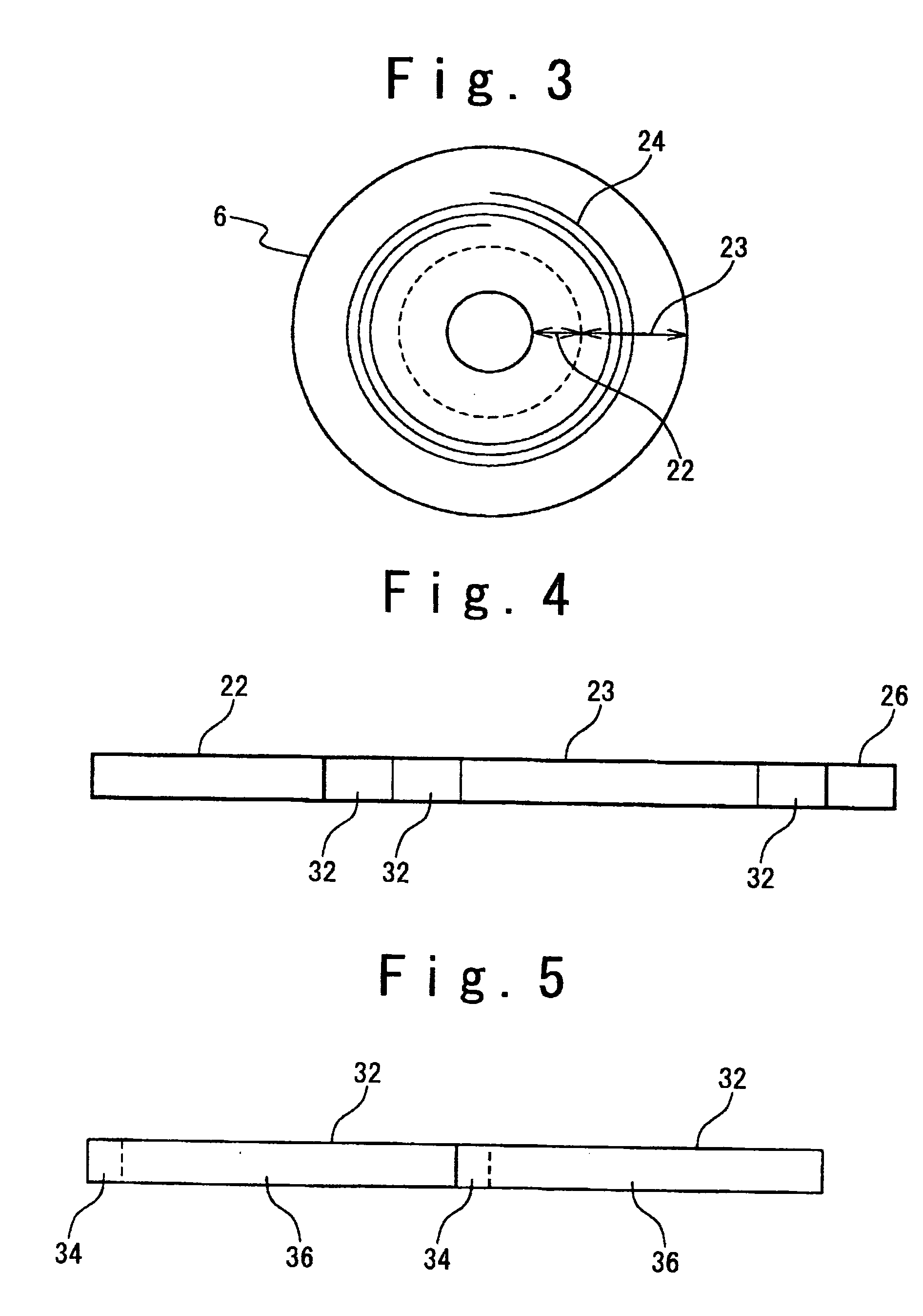
[0059] In the first embodiment, a flag area 34 is secured every this ECC block 32. As shown in FIG. 5, one flag area 34 is secured in the vicinity of a head position of one ECC block 32. Although only two blocks of the ECC blocks 32 are shown in FIG. 5, the ECC blocks have been continuously recorded on a track. Data indicative of a mode is recorded on a head flag recording position of each of these ECC blocks 32. There are two modes, namely a normal mode and an advance mode. In the normal mode, a series of user data which have been encoded are recorded in a continuous manner. In the advance mode, the control data which does not contain user data is recorded for an access control in a recording operation.

[0060] When the flag recorded in the flag area 34 indicates the advance mode, the control data is recorded in a data area 36 of the ECC block 32. When the flag area 34 is secured in each of the ECC blocks 32, the mode can be set in each of the ECC blocks 32. Thus, positions used to r...

second embodiment

[0092] In the second embodiment, a flag area 44 is set to a lead-in area 22. In the flag area 44, a flag indicative of the normal mode in which a series of user data which have been encoded are recorded in a continuous manner or a flag indicative of the advance mode, in which the control data which does not contain any user data is recorded because it is used for an access control in the recording operation. In this case, data indicating where the control data is located in the data recording area 23 is separately required. As the simplest method for indicating the position of the control data, there is a method for previously determining a position (address) of a data recording area which is used for the control data.

[0093] In the optical disk medium 6 shown in FIG. 6, a plurality of areas 42 where the control data will be recorded are arranged in a substantially constant interval along the radial direction of this optical disk medium 6 in the data recording area 23. Since the area...

third embodiment

[0111] In the third embodiment, a flag area 44 for recording a flag indicative of the normal mode and the advance mode is set to a lead-in area 22. In the normal mode, a series of user data which have been encoded are recorded in a continuous manner. In the advance mode, the control data which does not contain the user data is recorded for an access control in the recording operation. In this case, the data indicating where the control data is located within the data recording area 23 is separately required. As the simplest method for indicating the position of the control data, there is a method that when the write data is recorded in the data recording area 23, a position (address) of the data recording area used for the control data is determined, and the determined position for the control data is recorded in a predetermined area.

[0112] As shown in FIG. 7, an area 48 where the control data will be recorded is set within the data recording area 23, whereas the flag area 44 and th...


PUM

PropertyMeasurementUnit
diameteraaaaaaaaaa
diameteraaaaaaaaaa
areaaaaaaaaaaa

Abstract

An optical disk medium including a lead-in area and a data recording area. The data recording area includes a user data area where a user data is recorded which is to be recorded by a user, and a control data area where a control data is recorded, the control data being used in an access control operation of the optical disk medium.

Description

BACKGROUND OF THE INVENTION [0001] 1. Field of the Invention [0002] The present invention generally relates to an optical disk apparatus. More specifically, the present invention is directed to a recording type optical disk apparatus capable of recording / reproducing data by using a very small optical spot-beam, and an optical disk medium utilized in the recording type optical disk apparatus. [0003] 2. Description of the Related Art [0004] In an optical disk field for recording / reproducing data by using a very small optical spot-beam, CD-R (Compact Disk-Recordable) and DVD-R (Digital Versatile Disk-Recordable) disks corresponding to recording type optical disks on which are once capable of recording data have been widely popularized subsequent to a reproduction-dedicated ROM (Read-Only Memory) medium on which a data pit stream has been embossed. [0005] In a recording type optical disk medium, a groove track having a spiral shape is formed in an optical disk and used in a tracking ope...

Claims


Application Information

Patent Timeline
Patent Type & Authority Applications(United States)
IPC IPC(8): G11B7/0045G11B7/007G11B20/10G11B20/12G11B21/08
CPCG11B20/1217G11B2020/1222G11B2020/1267G11B2220/2562G11B2020/1285G11B2220/213G11B2220/215G11B2020/1275
Inventor YAMANAKA, YUTAKA
Owner NEC CORP
Why Eureka
Try Eureka