Pulse signal generator for ultra-wideband radio transception and radio transceiver having the same

a pulse signal and radio transceiver technology, applied in pulse techniques, phase-modulated carrier systems, amplitude demodulation, etc., can solve problems such as difficult equalizer realization, interference-induced performance degradation, and low output frequency range of general oscillators

Inactive Publication Date: 2005-06-30
ELECTRONICS & TELECOMM RES INST
View PDF11 Cites 32 Cited by
  • Summary
  • Abstract
  • Description
  • Claims
  • Application Information

AI Technical Summary

Benefits of technology

[0028] The baseband analog may comprise: a digital-to-analog converter (DAC) converting the signals out from the modulator to signals having an analog pattern; a low pass filter (LPF) outputting signals obtained by filtering signals having predetermined bands from the signals output from the DAC; and an amplifier amplifying levels of the signals output from the LPF up to a predetermined level and outputting the amplified signals.

Problems solved by technology

When UWB modules using the conventional DS-CDMA method, whose pulse widths are very narrow, are close within several cm, a performance degradation effect due to interference can occur.
However, it is difficult to realize an equalizer when a data transmission rate is high over hundreds Mbps.
However, a variable range of an output frequency of a general oscillator is not wide such as can accommodate all the frequency range required by a high speed WPAN standard, e.g., 3.1-10.6 GHz, and phase noise increases in proportion to an increase of an oscillator frequency range.
However, the PLL requires a certain time called a lock time until a frequency is changed and stable, and since the lock time is commonly taken over several micro seconds, it is difficult to obtain very fast (within several nano seconds) frequency hopping characteristics required in the multi-band pulse method or the FH-OFDM method with the PLL.
As the results, a UWB DS-CDMA method and the FH-OFDM method cannot be accommodated with one transceiver.

Method used


Image

  • Pulse signal generator for ultra-wideband radio transception and radio transceiver having the same
  • Pulse signal generator for ultra-wideband radio transception and radio transceiver having the same
  • Pulse signal generator for ultra-wideband radio transception and radio transceiver having the same

Examples


Embodiment Construction

[0050] Hereinafter, the present invention will now be described more fully with reference to the accompanying drawings, in which embodiments of the invention are shown.

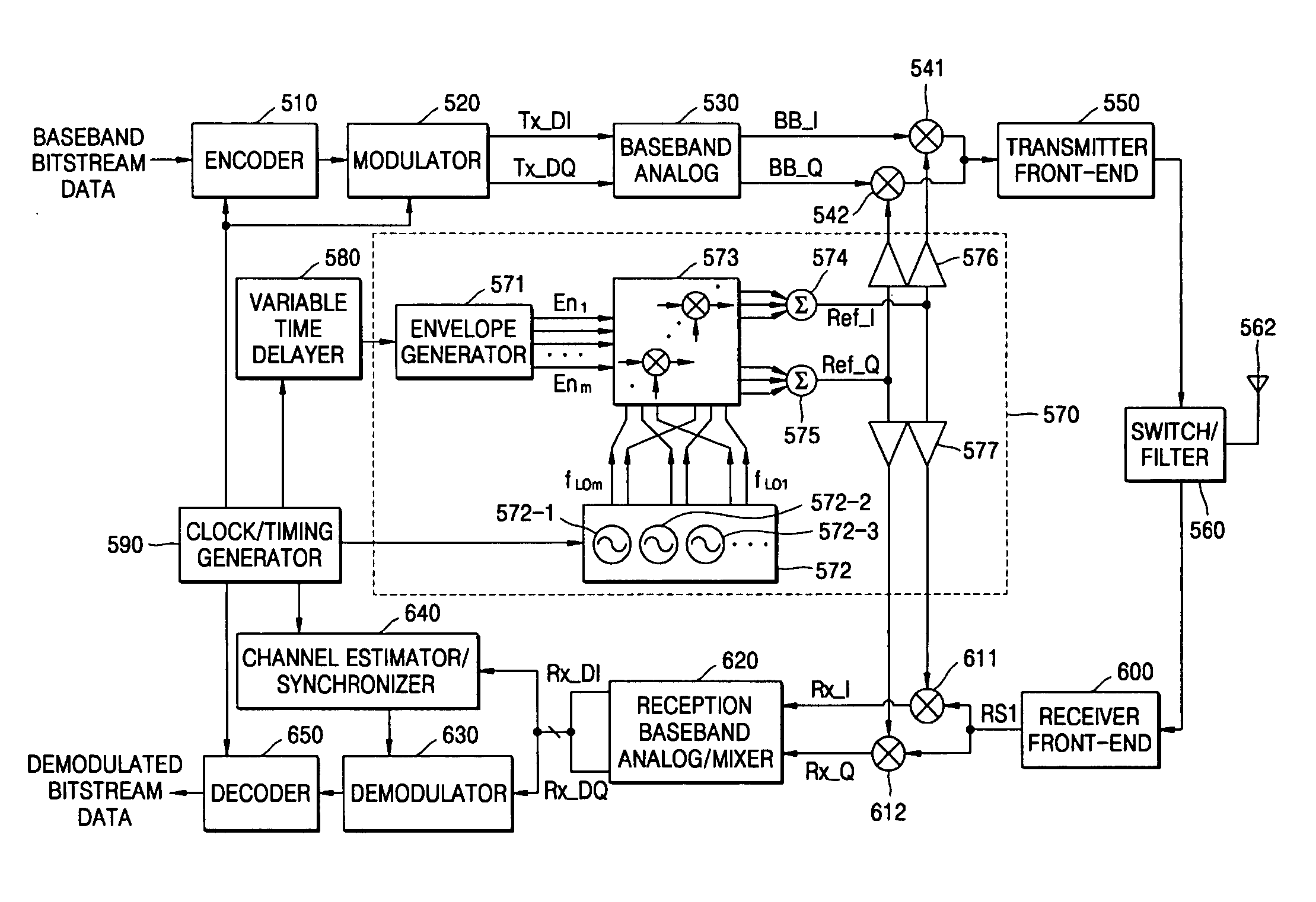
[0051]FIG. 5 is a block diagram of a pulse signal generator 570 and a UWB transceiver including the pulse signal generator according to an embodiment of the present invention. FIG. 6 is an embodiment of a multiplier array included in the pulse signal generator 570 of FIG. 5. FIG. 7 is a waveform diagram illustrating signal waveforms generated inside the pulse signal generator 570 of FIG. 5. FIG. 8 illustrates a power spectrum of an output signal among the signals illustrated in FIG. 7.

[0052] Referring to FIG. 5, the pulse signal generator 570 includes an envelope generator 571, which generates at least one waveforms having a predetermined pattern in a predetermined time period, a local oscillator array 572, which includes a plurality of oscillators and generates oscillation signals having independent frequencies, a ...


PUM


Abstract

Provided are a pulse signal generator for UWB radio transception and a radio transceiver having the same. The pulse signal generator includes: an envelope generator generating a plurality of envelope signals; a local oscillator array composed of a plurality of high frequency oscillators, each outputting two oscillation signals having a phase difference from each other; a multiplier array receiving the envelope signals and the oscillation signals and outputting signals obtained by respectively multiplying the envelope signals by the oscillation signals; and an I channel adder and a Q channel adder outputting an I channel pulse signal and a Q channel pulse signal by adding output signals having the same phase components among the signals output from the multiplier array, respectively.

Description

[0001] This application claims the priority of Korean Patent Application Nos. 2003-97246, filed on Dec. 26, 2003 and 2004-89721, filed on Nov. 5, 2004, in the Korean Intellectual Property Office, the disclosures of which are incorporated herein in their entirety by reference. BACKGROUND OF THE INVENTION [0002] 1. Field of the Invention [0003] The present invention relates to an ultra-wideband (UWB) radio device, and more particularly, to a pulse signal generator for UWB radio transception and a radio transceiver having the same. [0004] 2. Description of the Related Art [0005] According to increasing necessity of radio transmission performance and unique location awareness capability of ultra high speed multimedia data of hundreds Mbps through 1 Gbps classes, UWB radio technology is significantly considered in radio communication, imaging, and sensor fields. Basic structures of methods of carrier-free pulse radio devices using the UWB radio technology are already disclosed. Recently,...

Claims


Application Information

Patent Timeline
Patent Type & Authority Applications(United States)
IPC IPC(8): H04B1/38H04B1/40H04B1/717H04J13/00
CPCH04B1/7174H04L2025/0349H04L2025/03375H04B1/7183H04B1/40
Inventor HYUN, SEOK-BONGTAK, GEUM-YOUNGKIM, BYUNG JOPARK, KYUNG HWANHUR, JEENPARK, SEONG-SU
Owner ELECTRONICS & TELECOMM RES INST
Why Eureka
Try Eureka