Amplifying apparatus

a technology of amplifiers and amplifiers, applied in amplifier modifications to reduce non-linear distortion, baseband system details, gain control, etc., can solve problems such as noise in adjacent channels, distortion components, and distortion in the output signal of amplifiers, and achieve the effect of suppressing distortion components

Inactive Publication Date: 2005-06-30
FUJITSU LTD
View PDF3 Cites 22 Cited by
  • Summary
  • Abstract
  • Description
  • Claims
  • Application Information

AI Technical Summary

Benefits of technology

[0009] It is an object of the present invention to suppress distortion components contained in output signals of two amplifiers in a transient state as in a transi

Problems solved by technology

Against a backdrop of the proliferation of mobile communication terminals such as mobile phones and increased demand for high-speed data services, it presents a significant challenge to boost the transmission output of base stations and improve the reliability thereof.
A

Method used


Image

  • Amplifying apparatus
  • Amplifying apparatus
  • Amplifying apparatus

Examples


first embodiment

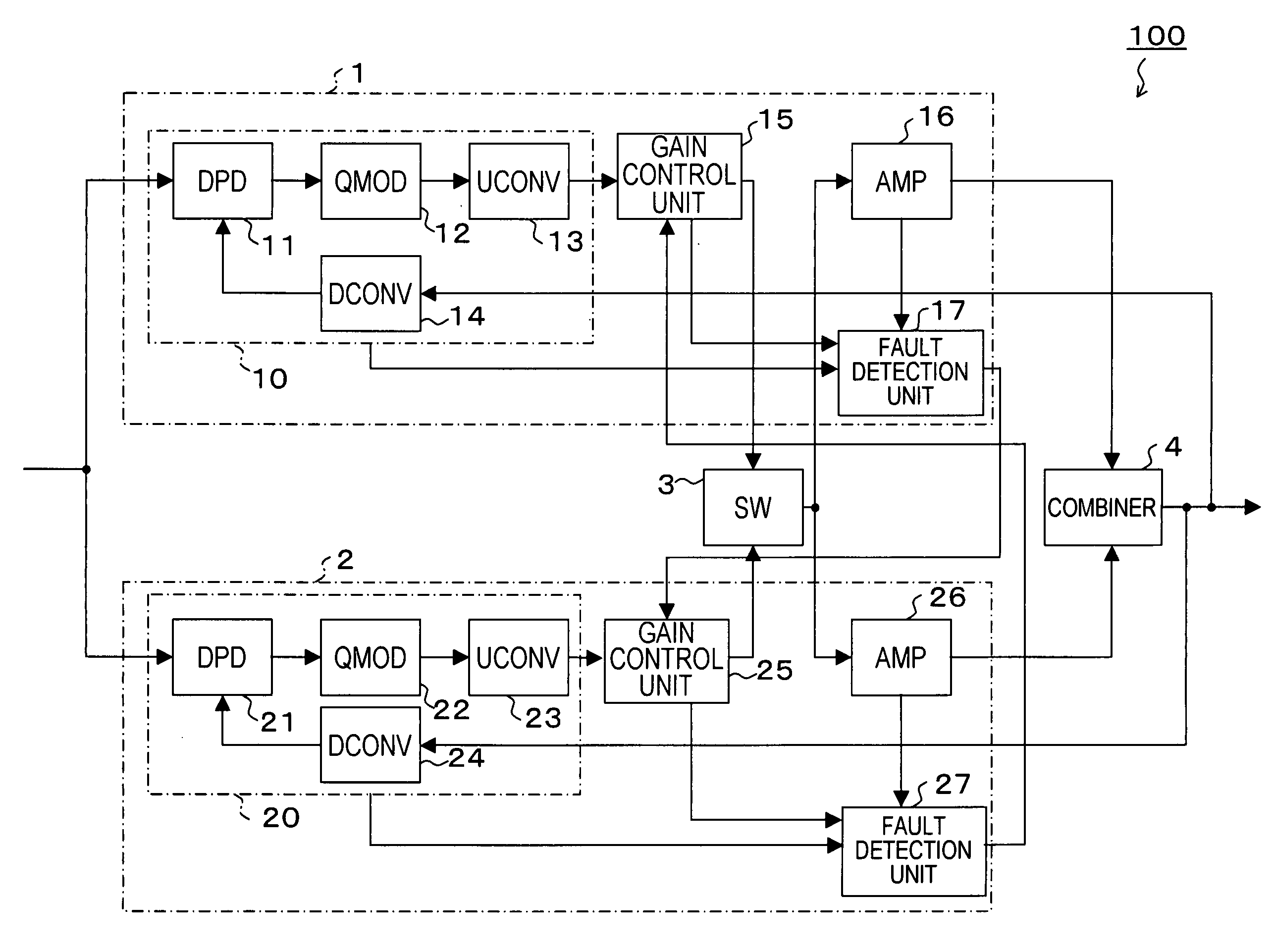
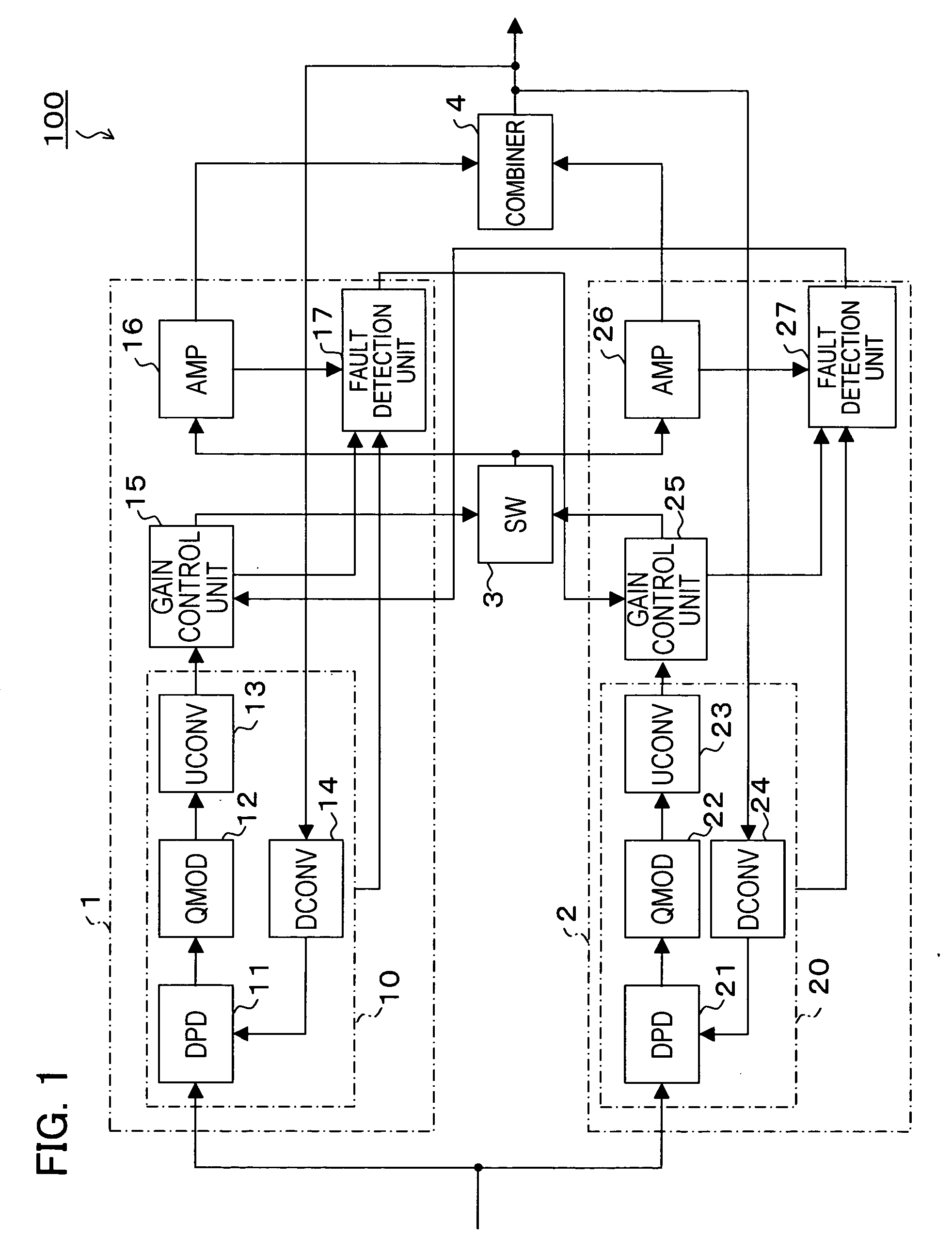
[0021]FIG. 1 is a block diagram showing a configuration of a transmission amplifying apparatus 100 according to a first embodiment of the present invention. The transmission amplifying apparatus 100 is provided, for example, at a base station of a mobile communication system and employed to amplify transmission signals to a mobile communication terminal.

[0022] The transmission amplifying apparatus 100 has transmission amplifiers 1 and 2, a switch (SW) 3 and a combiner 4.

[0023] The transmission amplifier 1 has a modulation unit 10, a gain control unit 15, a main amplifier (AMP) 16 and a fault detection unit 17. The modulation unit 10 has a digital predistorter (DPD) 11, a quadrature modulator (QMOD) 12, an upconverter (UCONV) 13 and a downconverter (DCONV) 14. These components of the transmission amplifier 1 are integrated, for example, into a single circuit board (card) or package.

[0024] Having the similar configuration as the transmission amplifier 1, the transmission amplifier ...

second embodiment

[0062]FIG. 3 is a block diagram showing a configuration of a transmission amplifying apparatus 200 according to a second embodiment of the present invention. The same symbols are used for the same components as those of the transmission amplifying apparatus 100 according to the first embodiment described earlier, and the description of the components will be omitted.

[0063] The transmission amplifying apparatus 200 has, in addition to the components of the transmission amplifying apparatus 100, a power measuring unit 18 in the transmission amplifier 1 and a power measuring unit 28 in the transmission amplifier 2. On the other hand, different symbols are used for gain control units 19 and 29 because the gain control units 19 and 29 partially differ in capabilities from the gain control units 15 and 25 of the transmission amplifying apparatus 100.

[0064] The power measuring unit 18 (28) finds the power value (input level) of the signal input to the modulation unit 10 (20), imparting t...

third embodiment

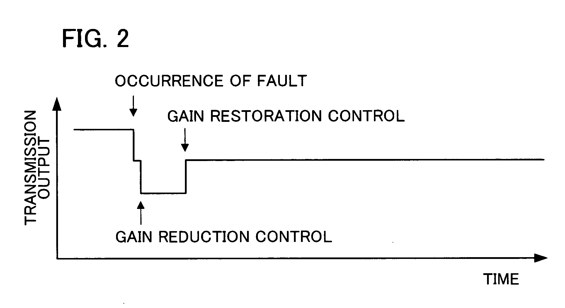
[0072] In the aforementioned first and second embodiments, the gain can be gradually restored to the steady value after the gain reduction control.

[0073]FIG. 4 is a graph showing changes in the transmission output (power value) from the combiner 4 before and after a fault in a third embodiment of the present invention. The transmission output declines by a constant value (e.g., 6 dB) immediately after the fault, as with the graph in FIG. 2. Thereafter, the transmission power diminishes as a result of the gain reduction control by the gain control unit 15 or 25 on the used side. The gain control unit 15 or 25 gradually restores the gain to the steady value over a constant time period, instead of doing so immediately, after the given time elapses from the gain reduction control.

[0074] This suppresses spectrum spreading of the transmission signal at the time of restoration of the gain to the steady value. As a result, the communication stability can be maintained while at the same ti...


PUM


Abstract

The present invention provides an amplifying apparatus including, two amplifiers for receiving input signals in common and for outputting their respective amplified signals, a combiner for combining the output signals of the two amplifiers and for outputting a combined signal, the amplifying apparatus which inhibit the distortion component in the output of amplifiers in the transition state. This amplifying apparatus comprises, a predistortion unit for determining a distortion compensation component based on the output of the combiner and for predistorting the input based on the determined distortion compensation component, and a gain control unit for attenuating the inputs to set lower than in the steady state by reducing the gain in the transition from two amplifier operation to one amplifier operation, or in the transition from one amplifier operation to two amplifier operation, or at the time of removal or attachment the amplifiers.

Description

TECHNICAL FIELD [0001] The present invention relates generally to an amplifying apparatus having two amplifiers each for amplifying a common input signal, and more particularly, to an amplifying apparatus for suppressing distortion components contained in output signals of the amplifiers in a transient state as in a transition from the state where both of the amplifiers operate to the state where either of the amplifiers operates. BACKGROUND ART [0002] Against a backdrop of the proliferation of mobile communication terminals such as mobile phones and increased demand for high-speed data services, it presents a significant challenge to boost the transmission output of base stations and improve the reliability thereof. [0003] To boost the transmission output while at the same time improving the reliability of the base stations, a configuration including two transmission amplifiers is contemplated. One of the reasons is that combining signals amplified by the two amplifiers offers a su...

Claims


Application Information

Patent Timeline
IPC IPC(8): H03F1/32H03F1/52H03F3/21H03G1/00H03G3/20H03G3/30H04K1/02
CPCH03F1/3241H03F1/3247H03F1/52H03F3/211H03G2201/504H03G3/3042H03G2201/103H03G2201/206H03G2201/307H03G1/0088
Inventor MARUYAMA, SATOSHI
Owner FUJITSU LTD
Why Eureka
Try Eureka