Method for inspecting mask

a mask and mask body technology, applied in the field of mask inspection, can solve the problem of high possibility of defect practically occurring on the body to be transferred, and achieve the effect of reducing the time elapsed by reviewing many pseudo defects or the like, and suppressing the detection of pseudo defects

Inactive Publication Date: 2005-06-30
RENESAS ELECTRONICS CORP
View PDF1 Cites 17 Cited by
  • Summary
  • Abstract
  • Description
  • Claims
  • Application Information

AI Technical Summary

Benefits of technology

[0023] According to the method, on the basis of judging result at the fourth step, it is possible to perform inspection with appropriate inspection accuracy depending on influence degree for a pattern to be transferred on a wafer of the defect. Consequently, it is possible to suppress detection of pseudo defects, and it is possible to certainly detect real defects. For this reason, time elapsed by reviewing many pseudo defects or the like is reduced, so that it is possible to perform speedy pattern inspection.

Problems solved by technology

For this reason, possibility that the defect practically occurs on the body to be transferred is high.

Method used


Image

  • Method for inspecting mask
  • Method for inspecting mask
  • Method for inspecting mask

Examples


Embodiment Construction

[0039] The invention will now be described herein with reference to illustrative embodiments. Those skilled in the art will recognize that many alternative embodiments can be accomplished using the teachings of the present invention and that the invention is not limited to the embodiments illustrated for explanatory purposed.

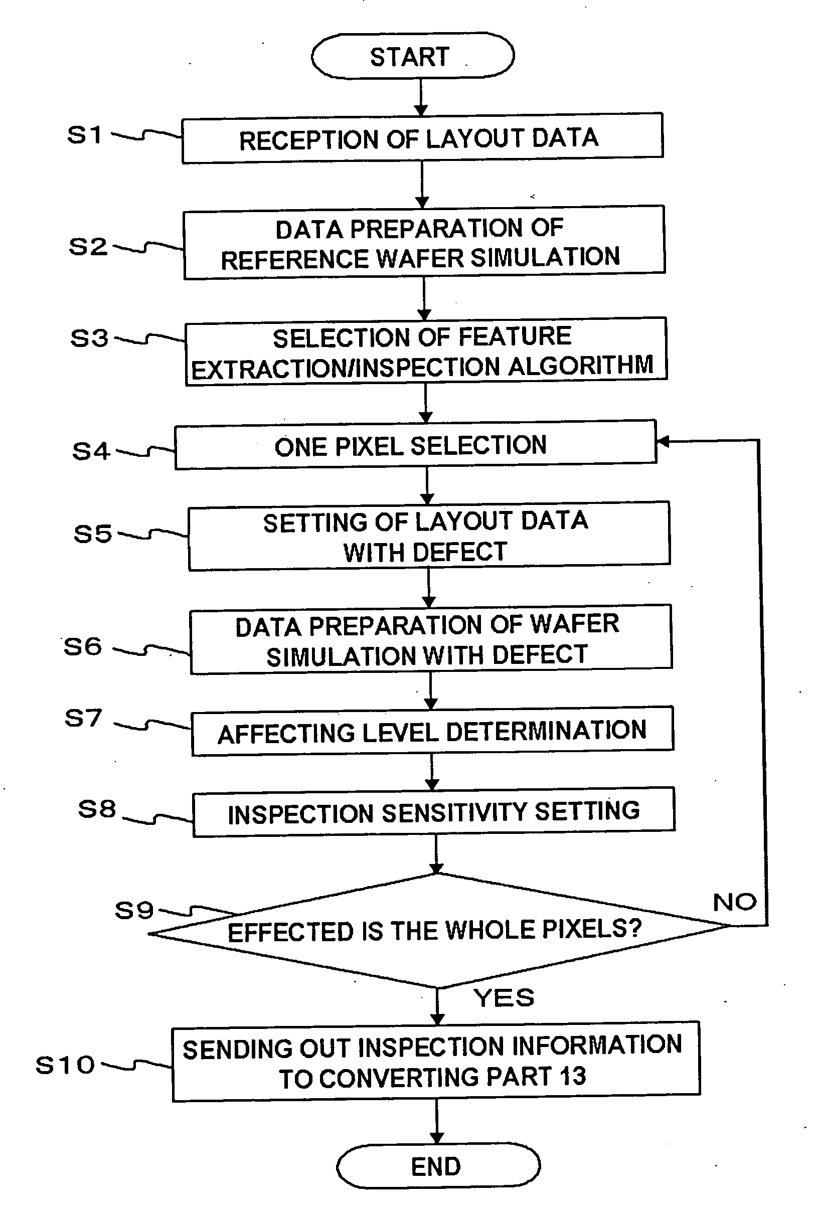
[0040] In the present invention, preferably, the size of pixel is not more than 100 nm×100 nm. In the present invention, preferably, the difference data is a difference data between the first virtual PR pattern data in every pixel and the second virtual PR pattern data. In the present invention, preferably, in the second step, the size of the defect in the defect pattern data is fixed to the predetermined size. In the present invention, preferably, in the fifth step, the larger pixel of the difference data, the smaller threshold value is set; and when the difference data between the real pattern data and the first layout data is larger than the threshold value,...


PUM

PropertyMeasurementUnit
sizeaaaaaaaaaa
sizeaaaaaaaaaa
defect sizeaaaaaaaaaa

Abstract

A mask inspection system 10 inspects an inspection object pattern while comparing an inspection object data obtained in such a way as to image the inspection object pattern with a reference pattern data. The mask inspection system 10 is provided with an inspection information preparing part 12 producing inspection algorithm and inspection sensitivity to the reference pattern data based on wafer simulation, a converting part 13 generating a reference graphic data with inspection information while adding the inspection information to the reference graphic data, and a defect judging part 16 judges propriety of an inspection object pattern data while comparing reference graphic data with an inspection object data in every pixel based on the inspection information added to the reference graphic data with inspection information.

Description

[0001] This application is based on Japanese patent application NO. 2003-432984, the content of which is incorporated hereinto by reference. BACKGROUND OF THE INVENTION [0002] 1. Field of the Invention [0003] The present invention relates to a method for inspecting a mask. [0004] 2. Description of Related Art [0005] Conventionally, as a method for inspecting a pattern (hereinafter referred to as mask pattern) on a mask or a reticle, adopted method is a method for detecting defects in such a way as to compare an inspection object data obtained by imaging a mask pattern with a design data (EB data) for an electron-beam direct drawing of the mask stored in a CAD. [0006] Here, FIG. 12 shows the conventional and general mask inspection system. The mask inspection system 30 is comprised of an inspecting part 31, a converting part 32, a rendering part 33, a comparing part 34, a defect judging part 35 and a reviewing part 36. [0007] The inspecting part 31 images a mask pattern of an inspect...

Claims


Application Information

Patent Timeline
Patent Type & Authority Applications(United States)
IPC IPC(8): G03F1/84G03F9/00G01N21/956G06K9/00G06T7/00
CPCG03F1/84G06T2207/30148G06T7/001
Inventor ANDO, AKIHIKO
Owner RENESAS ELECTRONICS CORP
Why Eureka
Try Eureka