Eureka AIR delivers breakthrough ideas for toughest innovation challenges, trusted by R&D personnel around the world.

Transmit power control method and radio arrangement

a power control and radio arrangement technology, applied in power management, transmission monitoring, electrical equipment, etc., can solve the problems of user equipment reducing its transmitter power, long feedback delay, and typical delay

Inactive Publication Date: 2005-06-30
NOKIA CORP
View PDF1 Cites 31 Cited by
  • Summary
  • Abstract
  • Description
  • Claims
  • Application Information

AI Technical Summary

Benefits of technology

[0011] The method and radio arrangement of the invention provide several advantages. For example, the power control of the radio arrangement is improved. Another advantage is that the transmit power of the user equipment is reduced timely and the communication quality is kept at a target level. Thus, the capacity of the radio arrangement supporting uplink fast closed loop power control and uplink soft handover is increased.

Problems solved by technology

Otherwise, the user equipment reduces its transmitter power.
In some systems, the uplink outer loop power control is centralizedly performed at the RNC, which brings more signalling between the RNC and the Node B and also long feedback delays of the SIR target, the feedback delay being typically hundreds of milliseconds.
A problem occurs in systems where outer loop power control is distributed in each base station in the following situation.
This is a problem especially in the known outer loop power control method in which small step sizes are used to adjust downwards.
During the time the SIR target value is being adjusted, the user equipment requests too high power.
This further leads to capacity degradation.
Also, when user equipment communicates simultaneously with two or more base stations, the performance of the system will degrade due to one or more useless power control channels.

Method used


Image

  • Transmit power control method and radio arrangement
  • Transmit power control method and radio arrangement
  • Transmit power control method and radio arrangement

Examples


Embodiment Construction

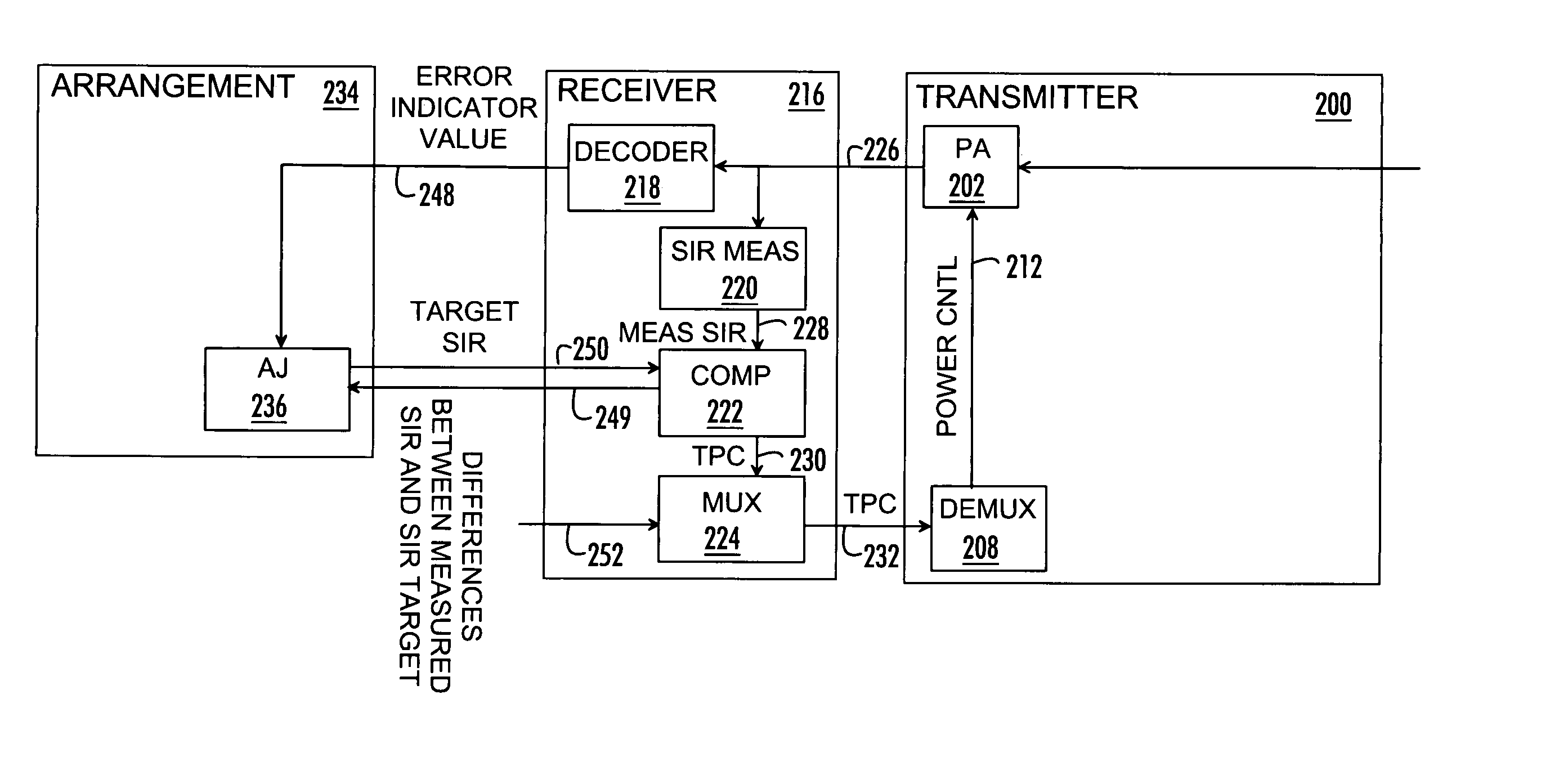
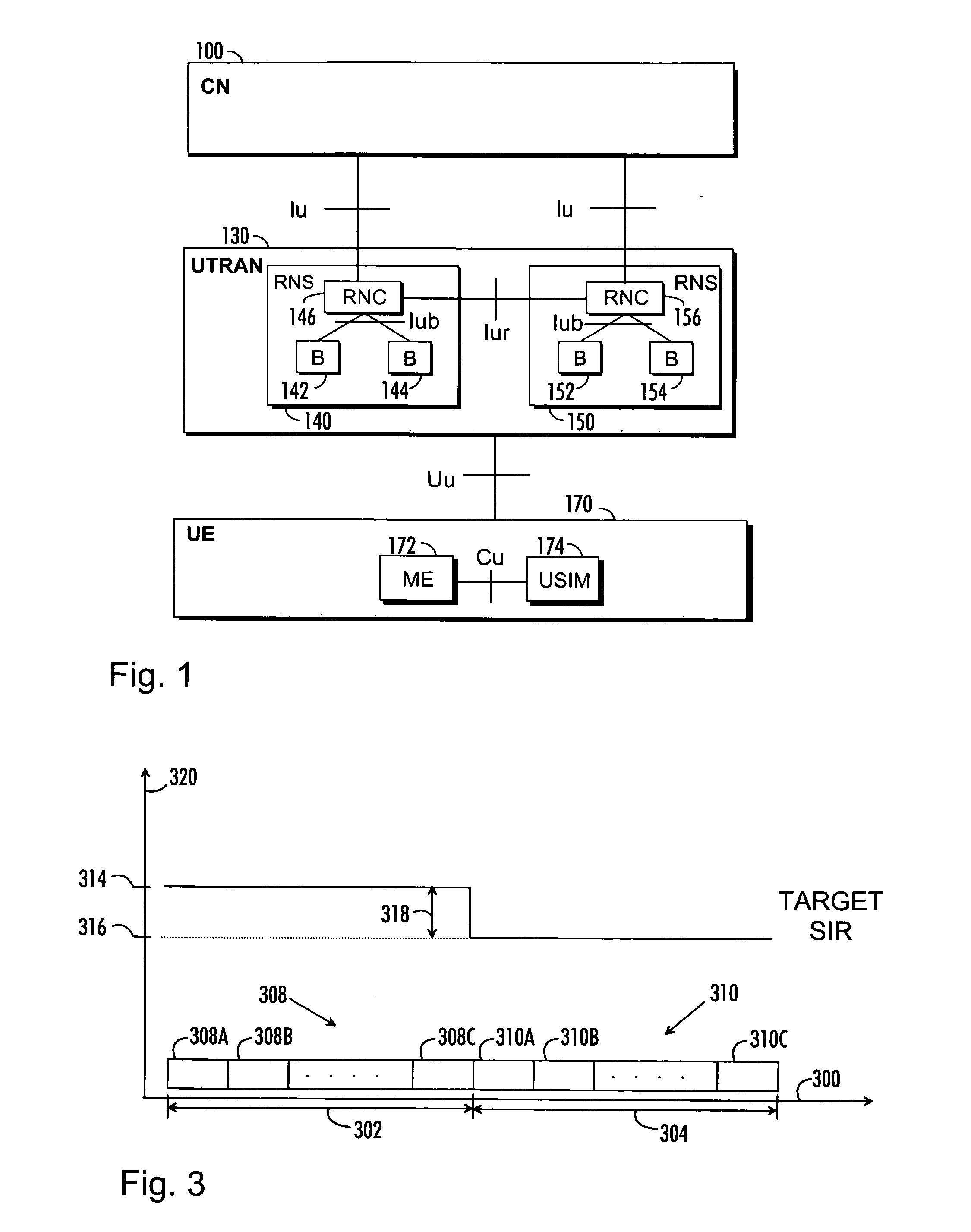
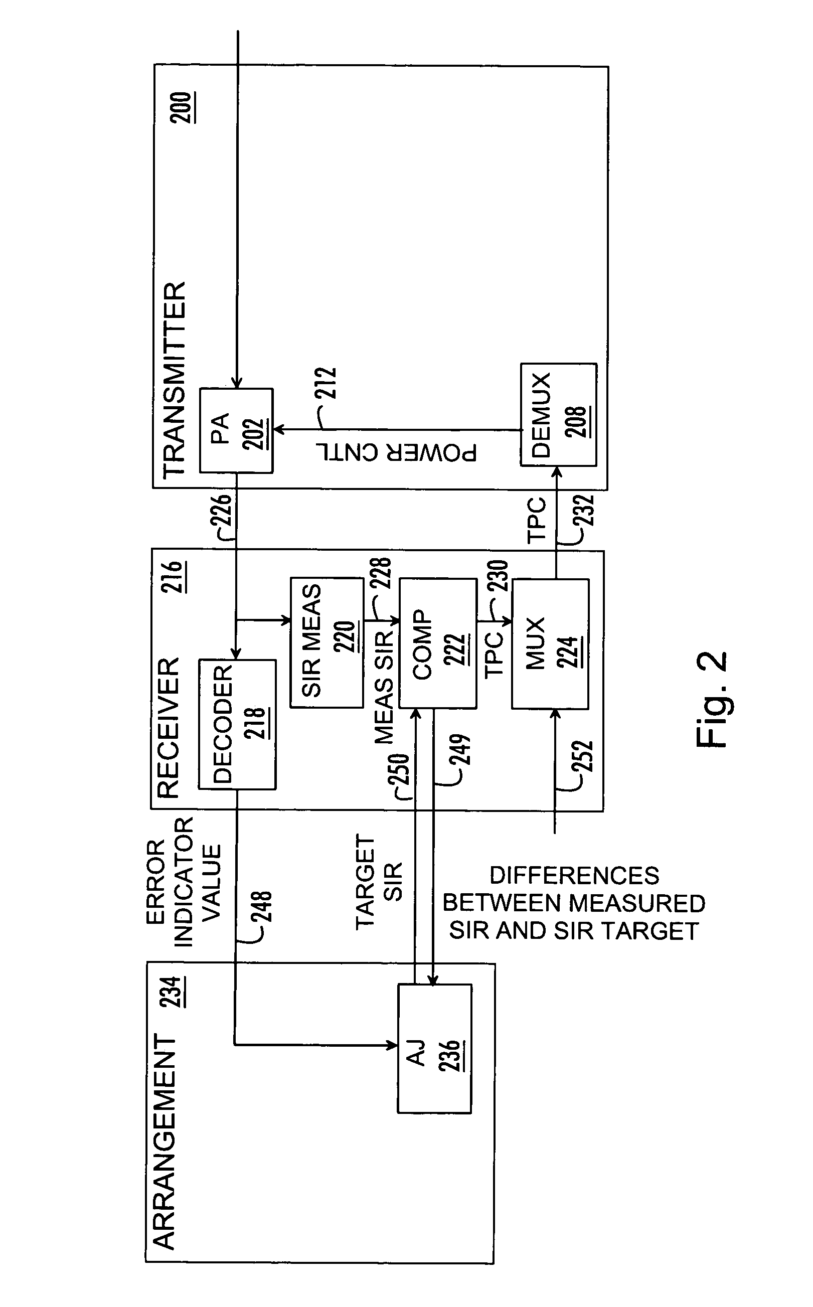
[0017]FIG. 1 illustrates an example of a radio system to which the embodiments of the invention can be applied. A radio system in FIG. 1, known at least as UTRAN [UMTS (Universal Mobile Telecommunications System) Terrestrial Radio Access Network]130, is taken as an example. The UTRAN belongs to the third generation and is implemented with WCDMA (Wideband Code Division Multiple Access) technology. The solution is not limited to a WCDMA radio interface but applications exist which are implemented with cdma2000, MC-CDMA (Multi-Carrier Code Division Multiple Access) or OF-DMA (Orthogonal Frequency Division Multiple Access) technologies without restricting the invention to the above-mentioned technologies.

[0018]FIG. 1 is a simplified block diagram which shows the most important parts of a radio system and the interfaces between them at a network-element level. The structure and functions of the network elements are not de-scribed in detail, because they are generally known.

[0019] The m...


PUM


Abstract

A radio and a transmit power control method in a radio system supporting a use of coding blocks in communication between a base station and user equipment is disclosed. The method comprises producing a measured SIR (signal-to-interference ratio) value and compares the measured SIR value with the target SIR value. Accordingly, the method also comprises determining the quality of the received coding blocks. The method also comprising storing samples of the differences between the measured SIR value and the target SIR value. The method also comprises adjusting the target SIR value based on the values of the samples of differences between the measured SIR value and the target SIR value and the quality of the received coding block. The method also comprises providing a transmit power control command based on the adjusted target SIR value to the user equipment.

Description

FIELD [0001] The invention relates to a transmit power control method and to a radio arrangement. BACKGROUND [0002] In some radio systems, such as in wireless CDMA (Code Division Multiple Access) communications systems, fast closed loop power control is used to overcome the negative effects caused by slow fading and partial negative effects caused by fast fading. The fast closed loop power control comprises inner and outer loop power control. The outer loop power control sets a SIR (signal-to-interference ratio) target, while the inner loop power control determines the command of increasing or decreasing the transmit power. A SIR is a ratio of the power of the required signal to that of interference. The values of the SIR target and the received / measured SIR are used in determining the power control commands for increasing or decreasing the transmit power. The SIR target may be a fixed or a dynamic value. The dynamic SIR target is advantageous over the fixed one. The method of setti...

Claims


Application Information

Patent Timeline
Patent Type & Authority Applications(United States)
IPC IPC(8): H04B1/04H04B7/005
CPCH04B2001/0416H04W52/24H04W52/12
Inventor GU, JIANHAMALAINEN, SEPPOWANG, DAQING
Owner NOKIA CORP
Why Eureka
Eureka Blog
Learn More