Dual antenna diversity transmitter and system with improved power amplifier efficiency

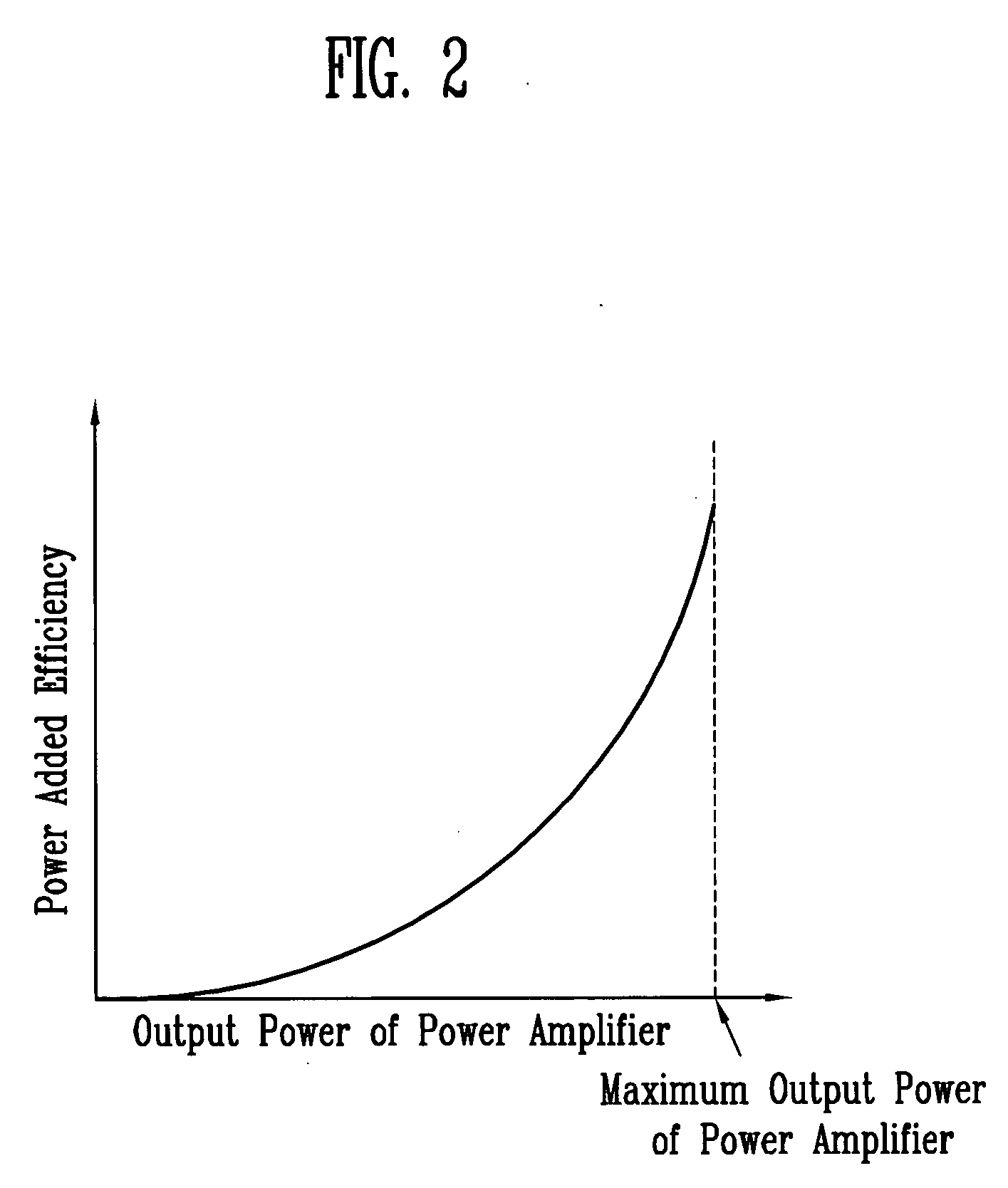
a technology of power amplifier efficiency and transmitter, which is applied in power management, polarisation/directional diversity, and polarisation/wave modulation. it can solve the problems of low power added efficiency, inputted bias current increases with an increase of the output power of the power amplifier, and the remaining range other than the maximum output power range shows extremely low power added efficiency. , the effect of simple configuration

Inactive Publication Date: 2005-06-30
ELECTRONICS & TELECOMM RES INST
View PDF10 Cites 56 Cited by
  • Summary
  • Abstract
  • Description
  • Claims
  • Application Information

AI Technical Summary

Benefits of technology

[0018] Therefore, the present invention is directed to a dual antenna diversity transmitter and system, which can minimize the power consumption of a power amplifier, maintain the signal linearity, and be simply configured, in case that high output power is not required.

Problems solved by technology

As illustrated above, the power amplifier 105 is composed of a number of transistors, whereby it has a problem that a bias current larger than that of a normal amplifier composed of a few transistors is always consumed.
Accordingly, there is a problem that the inputted bias current increases with an increase of the output power of the power amplifier.
Referring to FIG. 2, the power added efficiency gradually increases as the output power increases, and the remaining range other than the maximum output power range shows extremely low power added efficiency.
As such, the maximum probability of occurrence of the power amplifier is distributed in the intermediate output power range indicative of relatively low power added efficiency rather than the maximum output power range indicative of the maximum power added efficiency, thereby having a problem that the power amplifier is inefficiently operated during most duration of the use period of the power amplifier.
However, the aforementioned method has a problem that the bias point of the power amplifier changes, and thus, the output matching condition is changed, resulting in aggravating the linearity of the power amplifier 105.
Thus, it has a problem that a degree of improving the power added efficiency is very little.
For this reason, the second stage by-pass has a problem that the structural configuration of the power amplifier becomes complicated.
In addition, the switch and the bypass path should be configured on the signal path between the first stage 124 and the second stage 128 within the existing power amplifier circuit, so that it has a problem that this structure should be considered from when designing the power amplifier, and that it cannot be applied to the structure of the existing power amplifier.

Method used


Image

  • Dual antenna diversity transmitter and system with improved power amplifier efficiency
  • Dual antenna diversity transmitter and system with improved power amplifier efficiency
  • Dual antenna diversity transmitter and system with improved power amplifier efficiency

Examples


example 1

[0034]FIG. 6 is a block diagram illustrating a configuration of a dual antenna diversity system according to a first embodiment of the present invention.

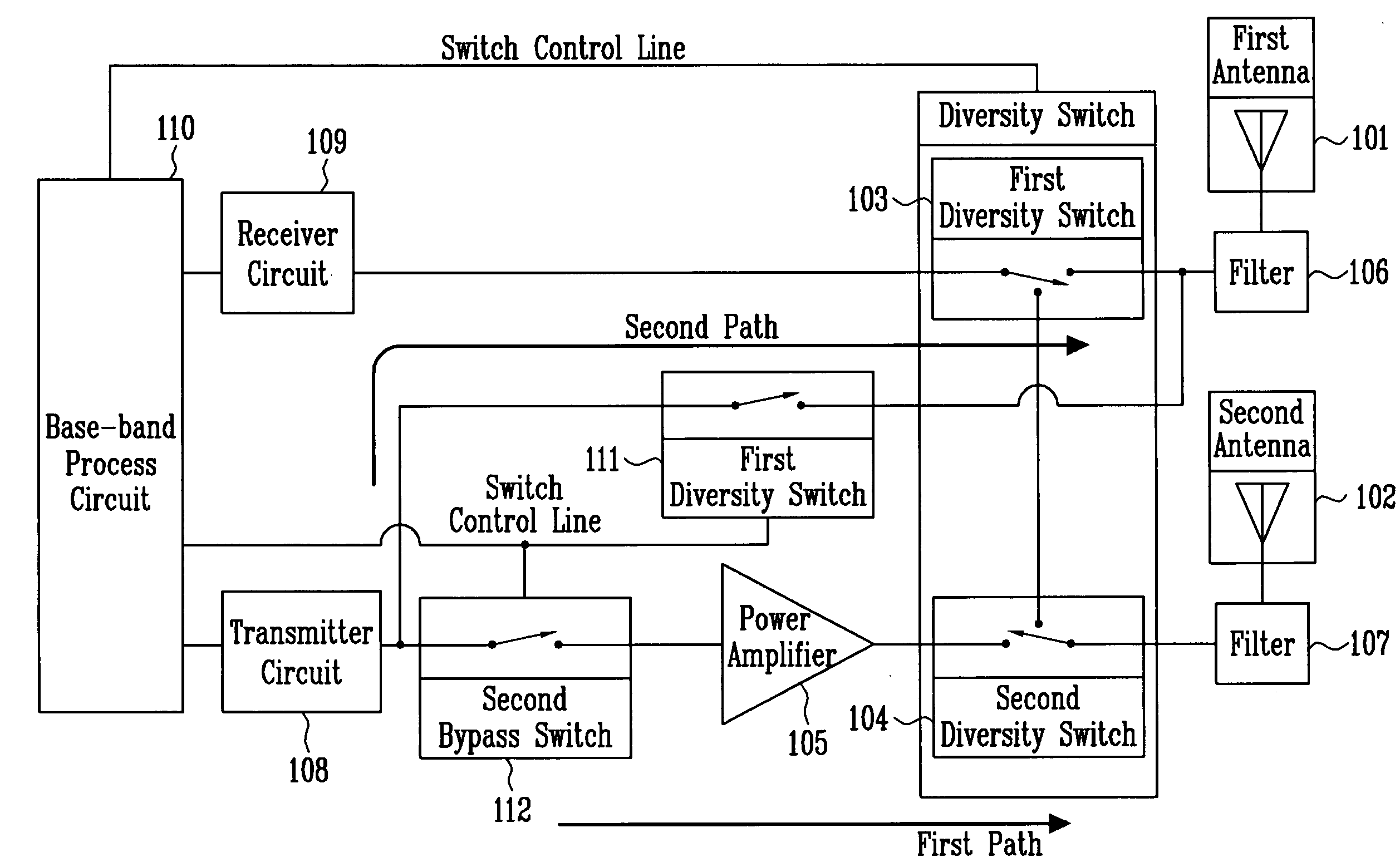
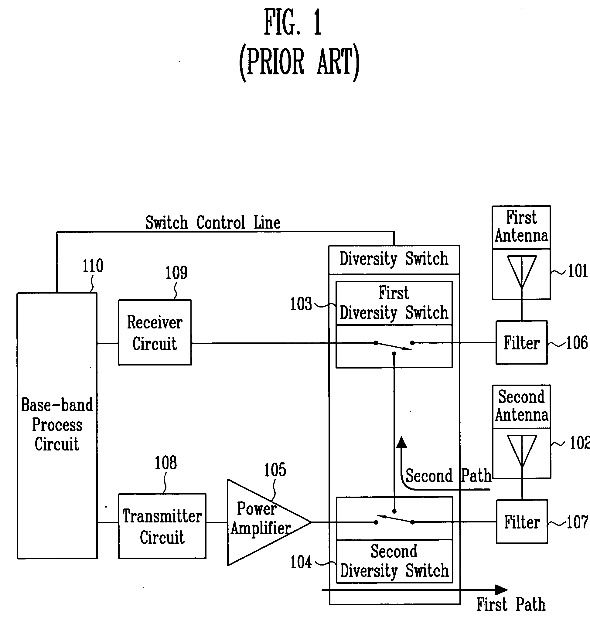
[0035] The dual antenna diversity system in FIG. 6, with the same manner as the prior art, comprises a first antenna 101 and a second antenna 102 for forming radio signal paths uncorrelated with each other on space or on antenna polarization and having the same antenna characteristics; a first diversity switch 103 and a second diversity switch 104 for switching a signal received by the two antennas; a power amplifier 105 for amplifying a transmitting signal power; a first filter 106 and a second filter 107 for removing an unnecessary signal; a transmitter circuit 108 for processing the transmitting signal, i.e., converting the base-band signal to a radio frequency signal; a receiver circuit 109 for processing a receiving signal, i.e., converting the radio frequency signal to the base-band signal; and a base-band process circuit 110...

example 2

[0039]FIG. 7 is a block diagram illustrating a configuration of a dual antenna diversity system according to a second embodiment of the present invention.

[0040] As shown in FIG. 7, the dual antenna diversity system of the second embodiment of the present invention is different from that of the first embodiment of the present invention in that it further comprises an amplifier 113 within the transmitter circuit 108. In case where the maximum output power of the transmitter circuit 108 is lower than the transmitting output power range where the probability of occurrence is high, the amplifier 113 is intended to make the power amplifier 105 operable with a configuration similar to the first embodiment, by making it possible to output the signal having the transmitting output power in which the probability of occurrence is high, with only the transmitter circuit 108. In this case, the output power of the installed amplifier 113 is significantly lower than that of the power amplifier 10...

example 3

[0041]FIG. 8 is a block diagram illustrating a configuration of a dual antenna diversity system according to a third embodiment of the present invention.

[0042] As shown in FIG. 8, the dual antenna diversity system according to the third embodiment of the present invention adds a power detector 114 in the output of the transmitter circuit 108 to the dual antenna diversity system according to the first embodiment of the present invention. The first bypass switch 111 and the second bypass switch 112 are controlled to be opened or closed, by detecting the output power of the transmitter circuit 108 through the power detector 114 and comparing this with the transmitting output power described in the first embodiment. With this operation, the switch is self-controlled by the power detector 114, contrary to the first embodiment where the first bypass switch 111 and the second bypass switch 112 are controlled by the base-band process circuit 110. Therefore, the efficient operation of the p...


PUM


Abstract

Provided is a dual antenna diversity transmitter and system having improved power amplifier efficiency, and further comprising switches in the dual antenna diversity transmitter and system, to minimize a DC input power consumed by the power amplifier depending on the required transmitting output power and operate efficiently the power amplifier, whereby signal linearity can be maintained and the power amplifier can be efficiently operated in a more simplified manner, as compared to the conventional high efficiency power amplifier.

Description

BACKGROUND [0001] 1. Field of the Invention [0002] The present invention relates to a dual antenna diversity transmitter and system and, more particularly, to a dual antenna diversity transmitter and system with high power amplifier efficiency. [0003] 2. Discussion of Related Art [0004] A dual antenna diversity method is intended to overcome a fading phenomenon due to a multi-path phenomenon of a radio signal in a wireless propagation environment. It forms two radio signal paths un-correlated with each other on space or on antenna polarization through two antennas, and then receives a signal through the minimum fading path between them. Many wireless communication systems widely used in an indoor environment where the fading phenomenon is serious, such as a wireless LAN, use such a dual antenna diversity system. [0005] Hereinafter, a conventional dual antenna diversity system will now be described with reference to FIGS. 1 to 3. [0006]FIG. 1 is a block diagram illustrating a configu...

Claims


Application Information

Patent Timeline
Patent Type & Authority Applications(United States)
IPC IPC(8): H04B1/02H04B7/005H04B7/06H04B7/08
CPCH04B7/0608Y02B60/50H04W52/52H04B7/0808H04B7/06
Inventor SUNG, JIN BONGKANG, SUNG WEONHYOUNG, CHANG HEEHWANG, JUNG HWANKIM, YUN TAE
Owner ELECTRONICS & TELECOMM RES INST
Why Eureka
Try Eureka