Yarn tension device

a tension device and tensioning technology, applied in the direction of looms, thin material processing, textiles and papermaking, etc., can solve the problems of not being able to have an unobstructed access or unobstructed access into the braking zone, affecting the efficiency of cleaning processes, and unable to have an unobstructed access or unobstructed view

Inactive Publication Date: 2005-07-07
IROPA AG (CH)
View PDF9 Cites 8 Cited by
  • Summary
  • Abstract
  • Description
  • Claims
  • Application Information

AI Technical Summary

Benefits of technology

[0006] It is an object of the invention to provide a yarn brake of the type as disclosed above which allows to fulfil the requirements occurring in practice in te

Problems solved by technology

Since the cover lid partly covers the braking zone even in the lifted position, it is not possible to then gain free access or to have an unobstructed view into the braking zone.
Since the braking zone cannot be cleared totally, neither unobstructed access nor

Method used


Image

  • Yarn tension device
  • Yarn tension device
  • Yarn tension device

Examples


Embodiment Construction

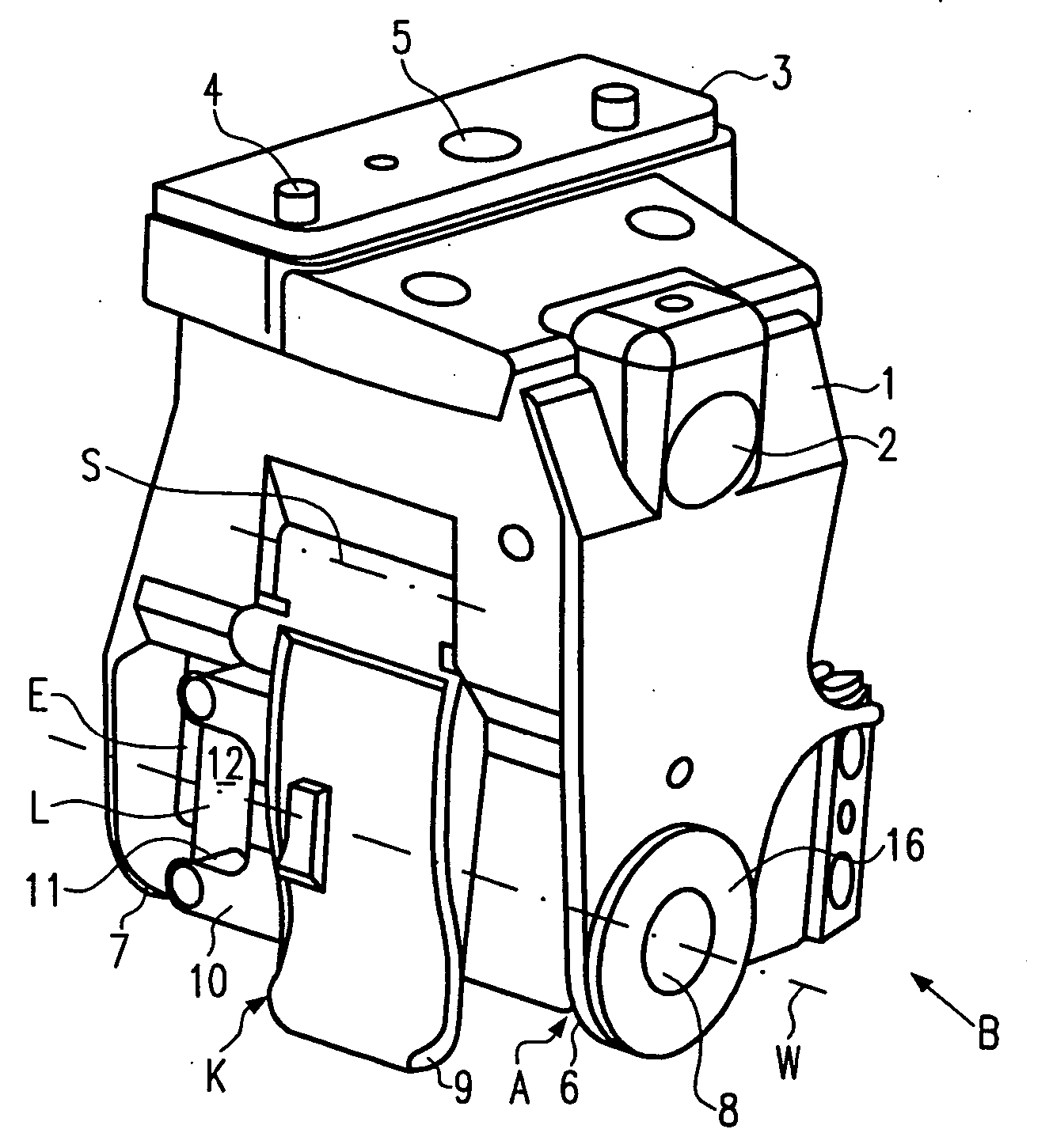
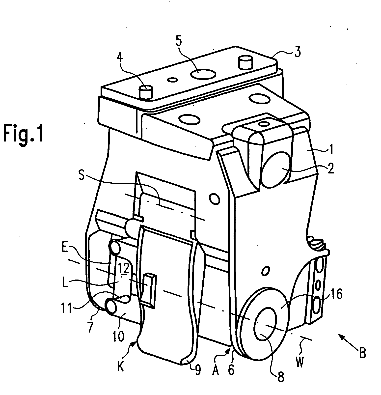
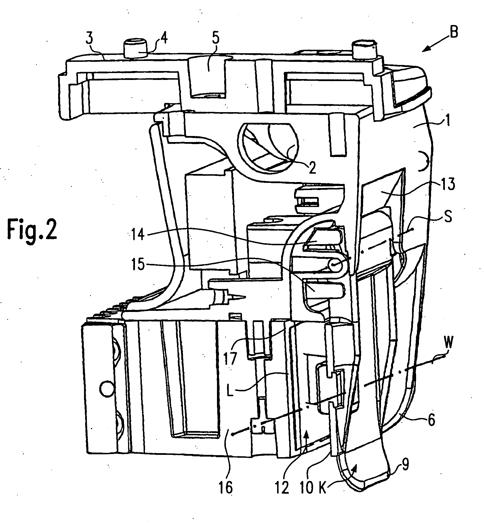
[0050] A yarn brake B has in FIGS. 1 and 2 a block-shaped housing 1 and an integrated solenoid housing 16. A lateral passage 2 of the housing serves to position the yarn brake B for operation, e.g. on a holding rod. Alternatively, the yarn brake B may be secured with the help of a fixation plate 3 e.g. at a housing bracket of a not shown yarn feeding device. Positioning pins 4 serve to safeguard the yarn brake mounting position. A port 5 for pressurised air, e.g. provided in the fixation plate 3, serves in some cases to supply pressurised air to a cleaning system of the yarn brake. The housing 1 includes side cheeks 6, 7 containing yarn guiding elements 8 (yarn eyelets) defining a yarn run path W through the yarn brake B. The braking zone 12 of the yarn brake B partially indicated in FIG. 1 is covered by a flap cover K. The flap cover can be tilted open about an adjusting arbor S of the housing 1. The adjusting arbor S is a tilting hinge. The flap cover K has a handle 9 which e.g. i...


PUM

PropertyMeasurementUnit
Angleaaaaaaaaaa
Angleaaaaaaaaaa
Pressureaaaaaaaaaa

Abstract

The invention concerns a yarn brake (B) comprising a brake (L) electromagnetically stressed against a fixed braking surface (17), a housing (1) whereon the cover bearing the brake (L) is mounted such that it is capable of being lifted relative to the fixed braking surface (17), and at least an adjusting arbor (S) controlling the lifting movements of the cover, said arbor being mounted on the housing (S) in geometric association to the path of the yam (W). The invention is characterised in that the cover is a flap cover (K) mounted so as to be capable of being lifted about the adjusting arbor (S) for completely clearing the braking zone (12) of the yam tension device (B).

Description

FIELD OF THE INVENTION [0001] The present invention relates to a yarn brake, and to a method of cleaning a yarn brake. BACKGROUND OF THE INVENTION [0002] The cover lid of the yarn brake for shuttleless weaving machines as known from EP 02 94 323 A (U.S. Pat. No. 4,875,506) can be lifted in parallel fashion from the fixed braking surface over a small stroke only and by means of two links. The links pivot against spring force about adjusting arbors which extend perpendicular to the yarn path. Since the cover lid partly covers the braking zone even in the lifted position, it is not possible to then gain free access or to have an unobstructed view into the braking zone. Alternatively, the braking lamella may be secured to an arbor which is fixed in the housing against rotation. The braking lamella is biased against the fixed braking surface. The braking zone cannot be cleared completely when the lamella is lifted by hand. [0003] The cover lid of the yarn brake according to EP 04 98 758 ...

Claims


Application Information

Patent Timeline
IPC IPC(8): B65H59/22D03D47/34
CPCB65H59/22B65H2301/531B65H2555/13D03D47/34B65H2601/524B65H2701/31B65H2601/321
Inventor JACOBSSON, KURT ARNE GUNNAROHLSON, PERGHIARDO, FIORENZOMAFFEO, ANDREA
Owner IROPA AG (CH)
Why Eureka
Try Eureka