Method and apparatus for treating particulate-shaped material, in particular for mixing, drying, graduating, pelletizing and/or coating the material

Inactive Publication Date: 2005-07-07
HUTTLIN HERBERT
View PDF5 Cites 7 Cited by
  • Summary
  • Abstract
  • Description
  • Claims
  • Application Information

AI Technical Summary

Benefits of technology

[0014] The invention is based on the object of developing a method and an apparatus of the type mentioned at the beginning with the effect

Problems solved by technology

However, since the moistening action cannot cover the entire material at the same time, a mixture of light powdery particles and heavier, moist and partly already agglomerated particles is formed in the particulate material.
In the known apparatus and the known process, the disadvantage consists in the fact that, because of the upwardly directed process air stream prevailing in the process chamber, the still powdery proportion of the material is carried along with the process air as the latter escapes from the process chamber and is thus removed from the process and, for exampl

Method used


Image

  • Method and apparatus for treating particulate-shaped material, in particular for mixing, drying, graduating, pelletizing and/or coating the material
  • Method and apparatus for treating particulate-shaped material, in particular for mixing, drying, graduating, pelletizing and/or coating the material
  • Method and apparatus for treating particulate-shaped material, in particular for mixing, drying, graduating, pelletizing and/or coating the material

Examples


Embodiment Construction

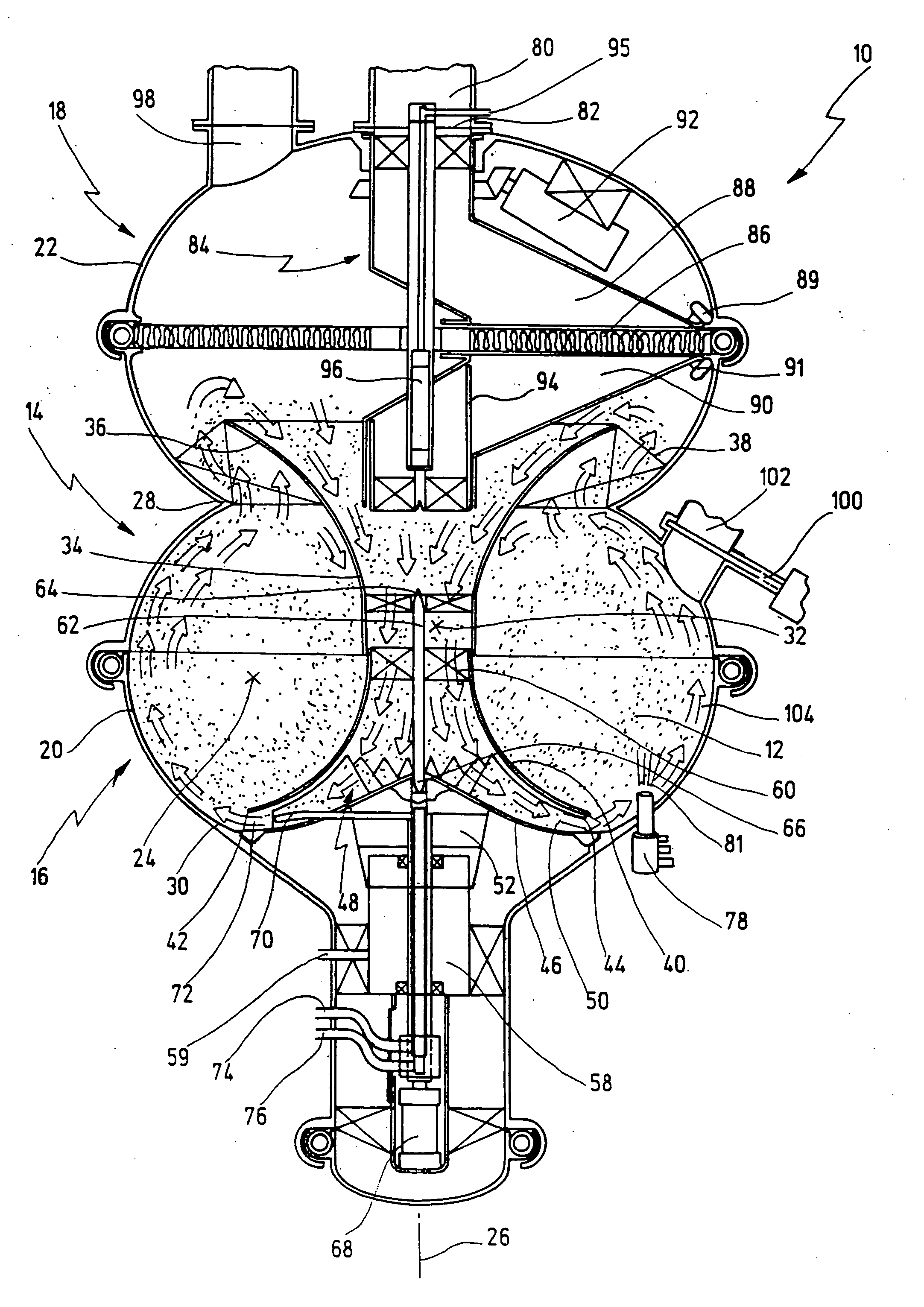
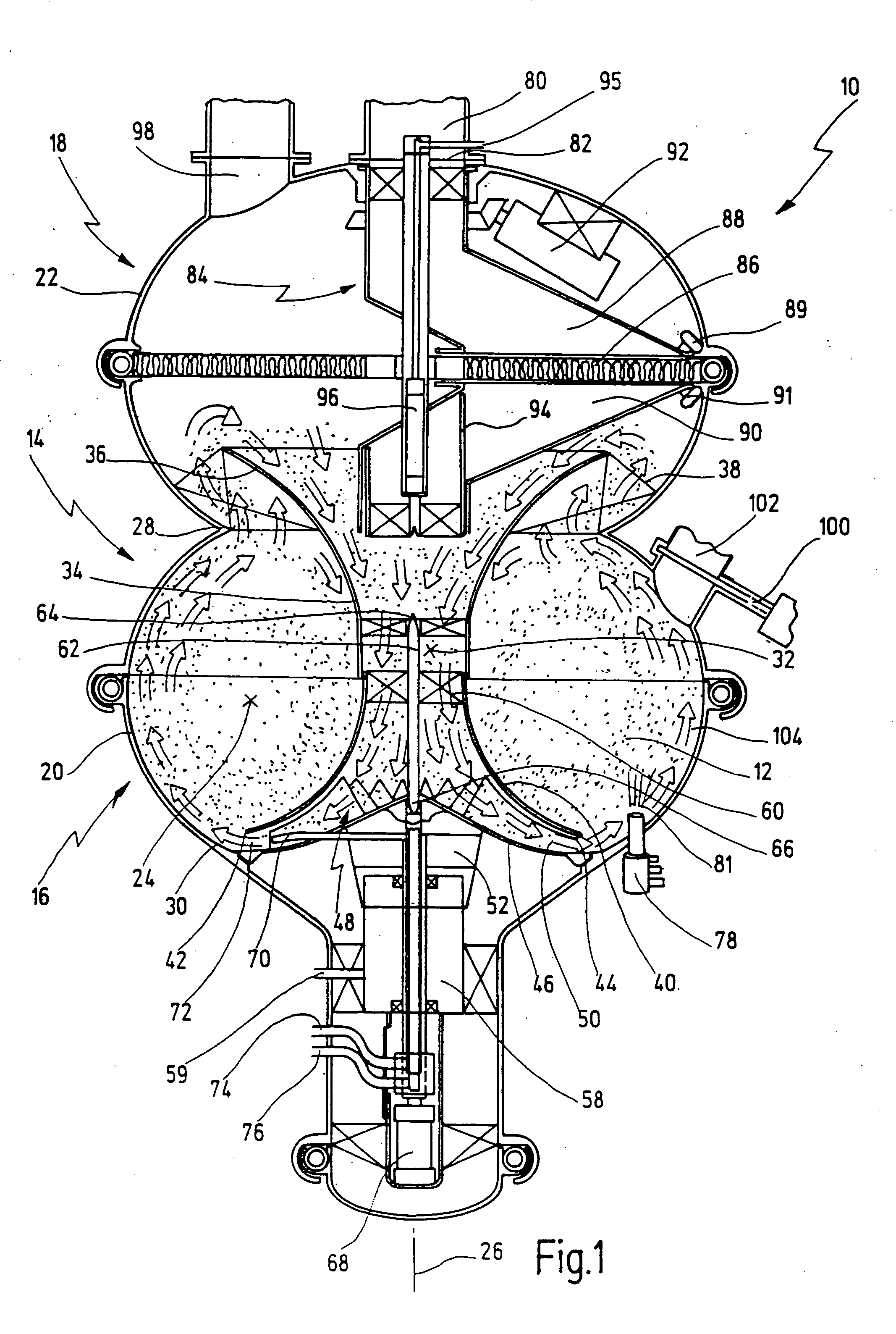
[0069] In FIG. 1, an apparatus for treating particulate material, in particular for mixing, drying, granulating, pelletizing and / or coating the material, is illustrated and provided with the general reference numeral 10. Further details of the apparatus 10 are illustrated in FIGS. 2 and 3.

[0070] In FIG. 1 and in FIG. 2, in order to illustrate the method still to be described later, which is carried out with the apparatus 10, the particulate material is illustrated by dots.

[0071] The apparatus 10 generally has a container 14. The container 14 has a first, lower container section 16 and a second, upper container section 18. Assigned to the first container section 16, on the outer circumference, is a first housing section 20, while the second container section 18 is assigned, on the outer circumference, a second housing section 22.

[0072] The container 14, more precisely, the first container section 16, has a process chamber 24 formed as an annular chamber. The process chamber 24 for...


PUM

PropertyMeasurementUnit
Timeaaaaaaaaaa
Pressureaaaaaaaaaa
Flow rateaaaaaaaaaa

Abstract

An apparatus for treating a particulate material, in particular for mixing, drying, granulating, pelletizing and/or coating the material, has a container which has a process chamber arranged around a longitudinal mid-axis of the container and formed as an annular chamber, and also a container central duct, separated from the process chamber, as a flow duct for process air, which duct opens into the lower region of the process chamber, an upper region of the process chamber being open. In at least one first operating state, the upper open region of the process chamber communicates with the container central duct so as to conduct process air, by the container central duct widening circumferentially towards the upper region of the process chamber and opening towards the process chamber. In a method for treating particulate material, the material is put into the container, and process air is introduced from the container central duct into the lower region of the process chamber and flows upwards in the process chamber in order to move the material in the process chamber. The process air emerges from the process chamber again from the upper region of the latter, the process air, at least in a first treatment phase, after emerging from the upper region of the process chamber, being led at least partly into the container central duct in a continued circulation-type flow and there being led downwards again, where it is introduced into the process chamber once more.

Description

CROSS REFERENCE TO OTHER APPLICATIONS [0001] The present application is a continuation of pending international patent application PCT / EP02 / 10175, filed on Sep. 11, 2002 which designates the United States, and which claims priority of German patent application 101 49 764.4, filed on Oct. 2, 2001.BACKGROUND OF THE INVENTION [0002] The invention relates to a method and to an apparatus for treating particulate material. [0003] The invention relates in particular to a method for treating and an apparatus for treating particulate material, which comprises mixing, drying, granulating, pelletizing and / or coating the material. [0004] The invention also relates to an apparatus for carrying out the aforementioned method. [0005] During granulating, the particles of the material, starting from a powdery state, are agglomerated to form larger particles by being moistened within the process chamber. [0006] During pelletizing, the material, likewise starting from a powdery state, is agglomerated t...

Claims


Application Information

Patent Timeline
IPC IPC(8): B01F33/40B01J2/16B01J8/30B01J8/38B01J8/44F26B3/092
CPCB01F13/0233B01F2003/1264B01J2/16F26B3/0926B01J8/386B01J8/44B01J2219/1942B01J8/30B01F23/566B01F33/405
Inventor HUTTLIN, HERBERT
Owner HUTTLIN HERBERT
Why Eureka
Try Eureka