Mechanical joints for subsea equipment

a technology for mechanical joints and equipment, applied in the direction of couplings, sealing/packing, borehole/well accessories, etc., can solve the problem of restricting the upper stiffness limits of the connection, and achieve the effect of reducing the uncertainty of the preload value inherent in the margin of error

Inactive Publication Date: 2005-07-07
FMC TECH INC
View PDF4 Cites 46 Cited by
  • Summary
  • Abstract
  • Description
  • Claims
  • Application Information

AI Technical Summary

Benefits of technology

[0009] The present invention provides a mechanical connector which in use applies a predetermined preload across a load transferring connection formed between parts of oil or gas well apparatus, characterised in that a component having a low modulus of elasticity in comparison to the remainder of the preload path is placed in the preload path so that the connector is adapted to accommodate larger dimensional tolerances in components forming the preload path for a given variation in the predetermined preload. This can be used to greatly reduce the margin of uncertainty in the preload value inherent in the variability of machining tolerances, wear, corrosion and assembly variances of the mating parts. Reduced uncertainty will allow a higher operating range for the connector. It will also allow the connector to be stiffer, providing much stronger connections. This uncertainty has previously restricted the upper stiffness limits for the connection.
[0010] The low modulus of elasticity of the component inserted within the load path greatly reduces the variation in stress / preload when compared to previous designs. The invention further allows a stiffer connector design with still improved setting tolerance.

Problems solved by technology

This uncertainty has previously restricted the upper stiffness limits for the connection.

Method used


Image

  • Mechanical joints for subsea equipment
  • Mechanical joints for subsea equipment
  • Mechanical joints for subsea equipment

Examples


Embodiment Construction

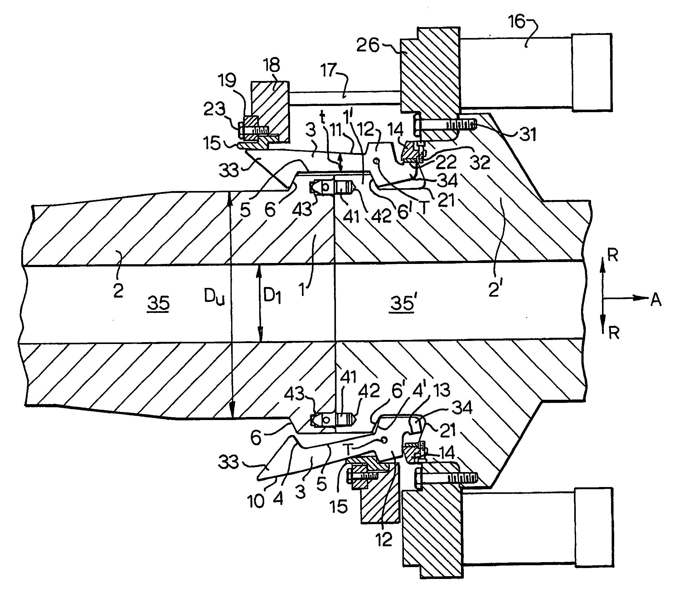
[0021]FIG. 1 shows two pipe components 2, 2′ each with a flow passage 35, 35′. The pipe components 2, 2′ may be parts of equipment that is part of an underwater pipe system for hydrocarbons. For example, the left component 2 can be a pipe while the right component 2′ can be a hub on a pressure tank. The pipe components each have a flange 1, 1′. By placing the flanges 1, 1′ facing each other as shown on FIG. 1, a connection or joint between the flow passages 35, 35′ is established, so that fluid can flow between the pipe components.

[0022]FIG. 1 also shows a pipe connector for clamping together the pipe flanges 1, 1′. The pipe connector has an axisymnetric shape for encircling the flanges 1, 1′, which are similarly configured. The axial direction A and radial directions R are indicated. In the following description the term “outwards” shall be understood as in the direction R, while the term “inwards” shall be understood as facing in the opposite direction to R. Correspondingly, the ...


PUM


Abstract

A mechanical connector for oil and gas well apparatus applies a predetermined preload across the connection, the preload being adapted to accommodate relatively large dimensional tolerances in the loadpath of the connector preload by placing a component with a low modulus of elasticity within that load path. In one embodiment, the connector comprises fingers (3) of a pair of pipe flanges (1, 1′), a stationary retainer ring (14) against which a finger reaction surface (13) is pressed, a runner ring (15) located outside the fingers and movable lengthwise along the fingers by an actuator (16), the retainer ring and the runner ring having an elasticity that is so large that deviations in their elongation only have a small influence on the retainer ring and the runner ring radial pressure against the fingers and clamping forces of the fingers against the flanges. In a second embodiment, the connector comprises dogs (103, FIG. 4) located around the circumference of a first tubular joint component, a follower located outside the dogs (103) and movable axially of the dogs, the low elastic modulus component being a ring located in the loadpath below the dogs. In a third embodiment, the connector comprises a lockdown mechanism acting between nested components, the low elastic modulus component being an insert comprising a load shoulder transferring loads between the nested components.

Description

BACKGROUND OF THE INVENTION [0001] The present invention relates to the use of a low modulus elastic insert as a component within the loadpath of load transferring structures. More specifically, the invention relates to connectors and joints for oil and gas wells having such inserts. [0002] Many joints are required to apply specific preload between two pieces of equipment. Variations in finished component dimensions lead to a potential variation in the applied preload when the joint is locked in place. These potential variations limit the load capacity of the joint, as the specified preload value must accommodate the uncertainty of the actual preload as well as the applied stress in the joint when in use. [0003] Many structures, when joined together, can experience large bending moments and / or tensile loads and must be highly preloaded in order to resist such loading. This is especially true for connectors used in subsea applications, such as pipeline collet connectors and wellhead ...

Claims


Application Information

Patent Timeline
Patent Type & Authority Applications(United States)
IPC IPC(8): E21B33/038F16L37/12F16L37/62
CPCE21B33/038F16L37/62F16L37/121F16L1/26
Inventor DAVIDSON, IAN MCCLYMONTSPITZ, STUART JANBARTLETT, CHRISTOPHER D.BEKKEVOLD, KNUT HAVARD
Owner FMC TECH INC
Why Eureka
Try Eureka