
Parametric amplification using two pump waves

a technology of parametric amplification and pump wave, which is applied in the direction of amplifiers, light demodulation, instruments, etc., can solve the problems of limiting the intensity of the pump wave and therefore the gain in opa b>100/b>, affecting the use of opas in optical communication systems, and spectral width of its gain band may be relatively narrow

Inactive Publication Date: 2005-07-07
LUCENT TECH INC +1
View PDF4 Cites 16 Cited by
  • Summary
  • Abstract
  • Description
  • Claims
  • Application Information

AI Technical Summary

Benefits of technology

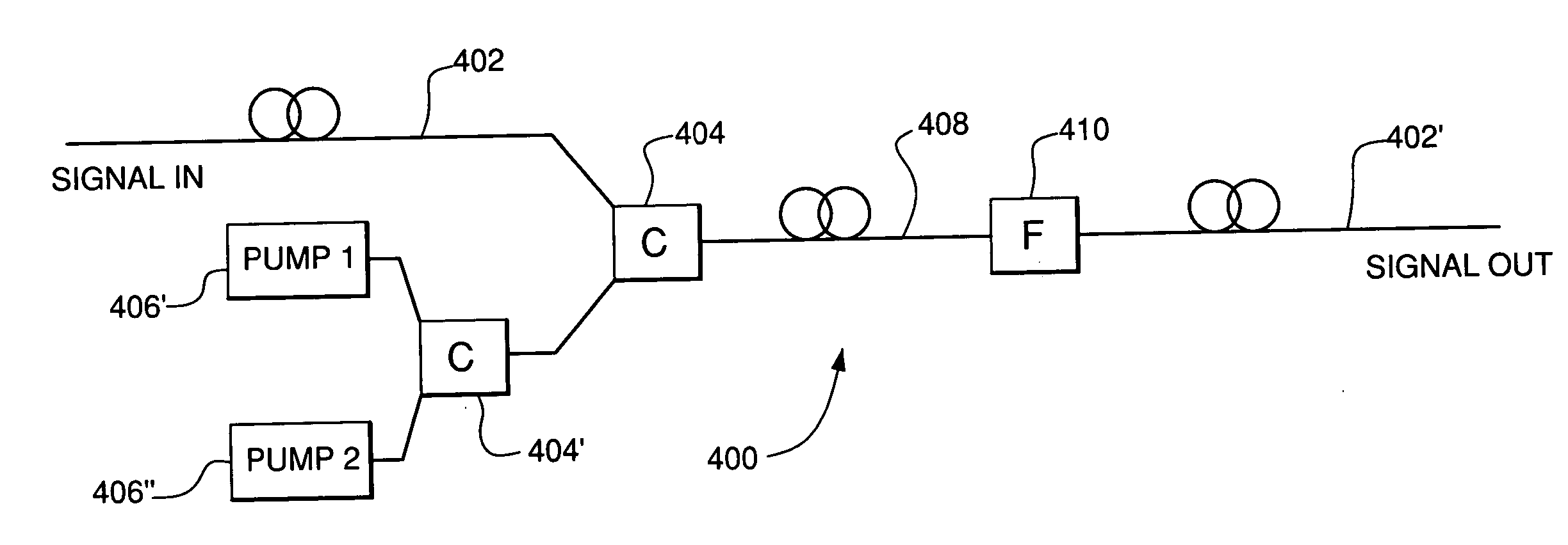
The present invention provides an optical parametric amplifier (OPA) that can be driven with at least two pump waves. These pump waves produce uniform exponential gain over a range of wavelengths that extends at least -30 nm on either side of the average pump-wave wavelength. This results in significantly more energy pumped into the OPA compared to a single pump wave of the prior art. The invention can be used in a wavelength division multiplexing (WDM) communication system for simultaneous signal amplification and wavelength conversion. The nonlinear optical medium used in the invention has a zero-dispersion frequency and is adapted to generate the amplified output signal through optical parametric amplification based on an optical Kerr effect. The spectral separation between the first and second pump waves is greater than about 10 nm or the frequencies of the first and second pump waves are asymmetrically offset with respect to the zero-dispersion frequency. The invention provides an improved optical amplifier with higher efficiency and greater flexibility for wavelength conversion.

Problems solved by technology

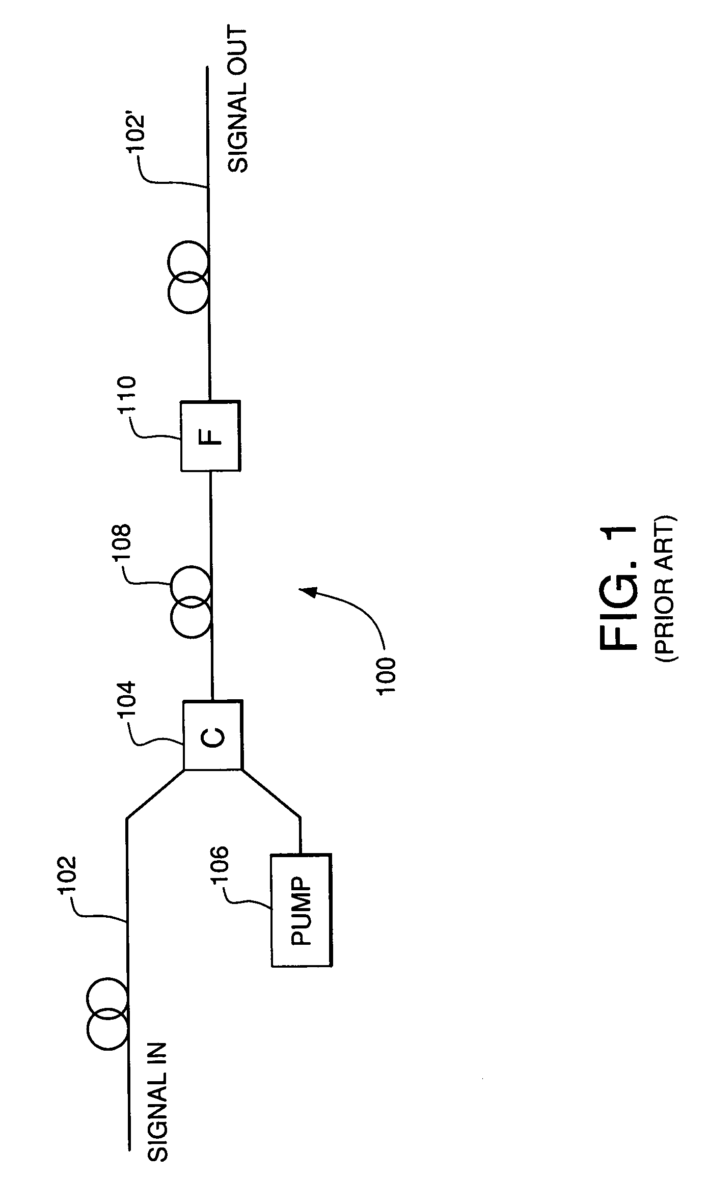
However, one problem with OPA 100 is that the spectral width of its gain band may be relatively narrow.
One additional problem is that the intensity of the pump wave and therefore the gain in OPA 100 are limited by Brillouin scattering.
These problems impede the use of OPAs in optical communication systems.

Method used


Image

  • Parametric amplification using two pump waves
  • Parametric amplification using two pump waves
  • Parametric amplification using two pump waves

Examples


Embodiment Construction

[0025] Reference herein to “one embodiment” or “an embodiment” means that a particular feature, structure, or characteristic described in connection with the embodiment can be included in at least one embodiment of the invention. The appearances of the phrase “in one embodiment” in various places in the specification are not necessarily all referring to the same embodiment, nor are separate or alternative embodiments mutually exclusive of other embodiments.

[0026] Before embodiments of the present invention are described in detail, different factors affecting the performance of prior art OPA 100 of FIG. 1 are briefly characterized.

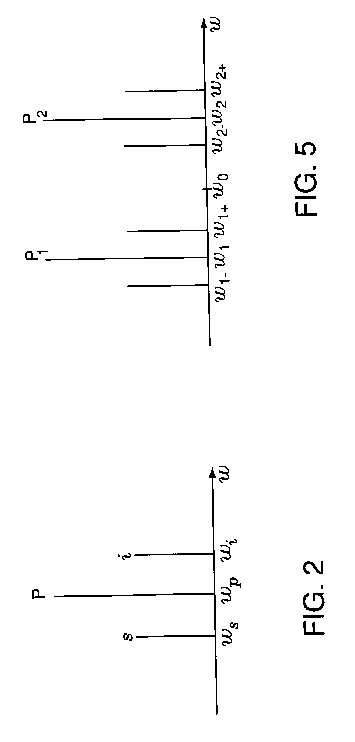
[0027]FIG. 2 illustrates the process of parametric amplification in OPA 100. Signal amplification in OPA 100 is governed by a degenerate four-wave mixing (FWM) process, in which two pump photons (labeled P in FIG. 2) combine to generate one signal photon and one idler photon (labeled s and i, respectively, in FIG. 2) according to the following equation:

2...


PUM

PropertyMeasurementUnit
wavelengthsaaaaaaaaaa
zero-dispersion wavelengthaaaaaaaaaa
zero-dispersion frequencyaaaaaaaaaa

Abstract

An optical parametric amplifier (OPA) driven with at least two pump waves. The pump waves may be configured such that the OPA produces uniform exponential gain over a range of wavelengths that extends, for example, at least 30 nm on either side of the average pump-wave wavelength. In addition, since the Brillouin scattering limit applies to each pump wave independently, substantially twice the amount of energy may be pumped into an OPA of the present invention compared to that in the corresponding single pump-wave OPA of the prior art. An OPA of the present invention may be used in a WDM communication system and configured for simultaneous signal amplification and wavelength conversion.

Description

[0001] CROSS-REFERENCE TO RELATED APPLICATIONS [0002] This application is a continuation-in-part (CIP) of U.S. patent application Ser. No. 10 / 232,082, filed Aug. 30, 2002, the teachings of which are incorporated herein by reference.BACKGROUND OF THE INVENTION [0003] 1. Field of the Invention [0004] The present invention relates to optical communication equipment. [0005] 2. Description of the Related Art [0006] Optical communication systems employ optical amplifiers, e.g., to compensate for signal attenuation in optical fibers. One type of amplifier that may be used in a fiber-based optical communication system is an optical parametric amplifier (OPA). As known in the art, an OPA is a device that produces a tunable coherent optical output via nonlinear optical processes, in which, typically, one or two pump-wave photons are converted into two new photons with conservation of photon energy and momentum. The waves corresponding to the two new photons are usually referred to as a signal...

Claims


Application Information

Patent Timeline
Patent Type & Authority Applications(United States)
IPC IPC(8): G02F1/39
CPCG02F1/397G02F1/395
Inventor MCKINSTRIE, COLIN J.RADIC, STOIAN
Owner LUCENT TECH INC
Learn More