Method of applying a cover layer to a structured base layer

Inactive Publication Date: 2005-07-07
LPKF LASER & ELECTRONICS
View PDF4 Cites 1 Cited by
  • Summary
  • Abstract
  • Description
  • Claims
  • Application Information

AI Technical Summary

Benefits of technology

[0013] A particular object of the invention is to provide a method for applying a cover layer to a base layer in which inaccuracies in the correlation between the cover layer and the base layer are prevented.
[0029] In one particularly advantageous embodiment of the invention, the base layer and / or cover layer is a film which allows winding and unwinding from one roll to the next. This can greatly facilitate subsequent manufacturing processes because of the units available on the roll.

Problems solved by technology

In practice, however, unavoidable elongation in length of the cover layer or the base layer has proven to be problematical, so that there may be deviations in the correlation between the opening and the structuring.
At the same time, these deviations also lead to deviations in the subsequent structuring.
However, this method is complex and cannot always prevent the occurrence of errors and thus cannot prevent rejects.
Another problem is that the contours of the passage cannot be selected at will by the rotary cutting blade because the areas to be removed are separated cohesively as a film from the cover layer.
In particular, therefore, it is impossible to implement openings in the form of “islands” without any connection to the subsequent opening.
Furthermore, production of the altered structuring necessitates shutdown and renewed setup of the equipment.
In particular, production of different structuring and different passages accordingly can be performed only to an extremely limited extent and the production of individual structuring is completely impossible.

Method used


Image

  • Method of applying a cover layer to a structured base layer
  • Method of applying a cover layer to a structured base layer

Examples


Embodiment Construction

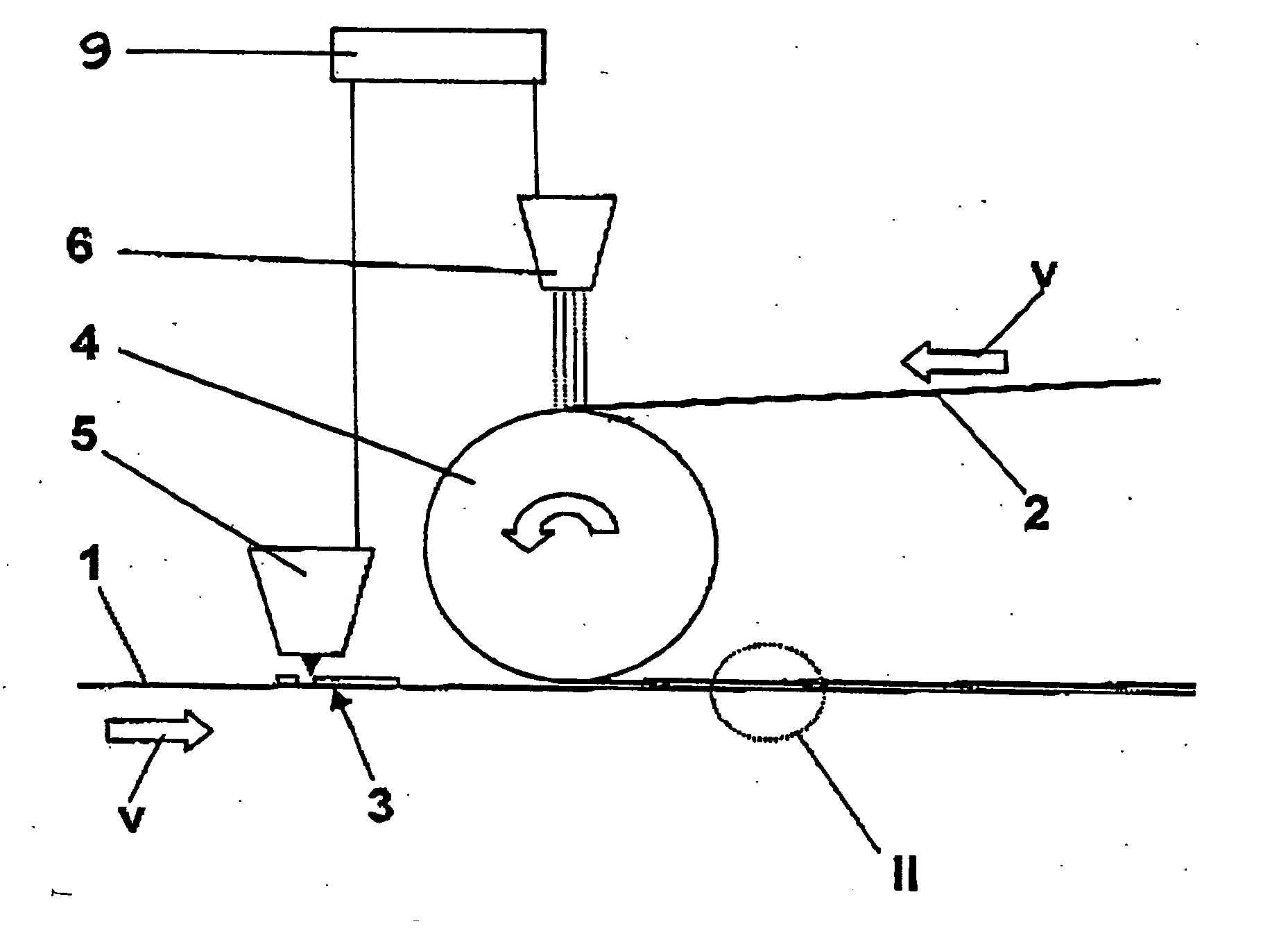
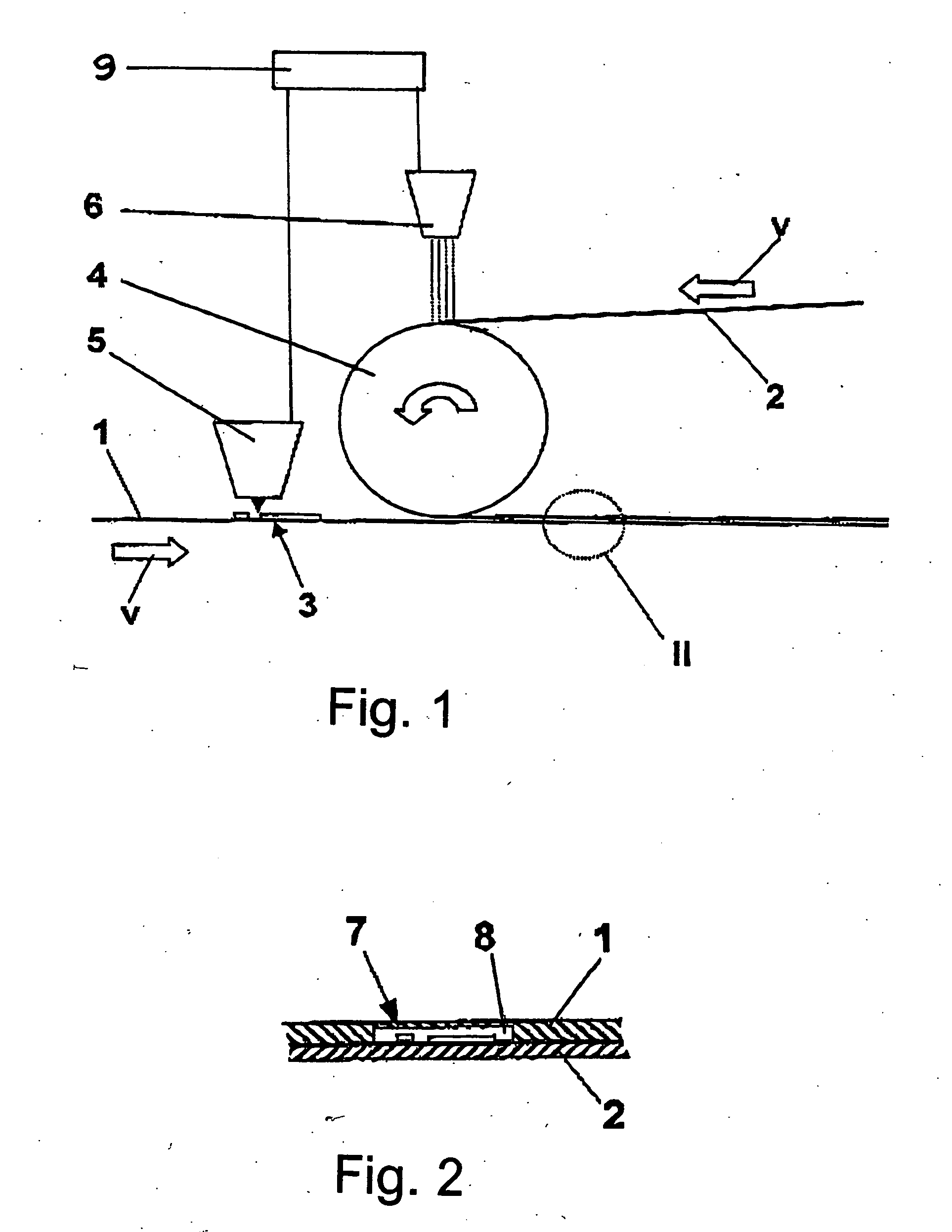
[0035]FIG. 1 shows a method of applying a cover layer 1 to a base layer 2, which is provided with a structuring 3 comprised of printed conductors, for example. The base layer 2 is moving at a feed rate v in continuous operation. By means of a guide 4, which is designed as a rotatable body, the cover layer 1 is brought to the matching feed rate v and is applied to the base layer 2. The position of the structuring 3 on base layer 2 is determined directly by a non-contact sensor 5 and transmitted to a control unit 9. The control unit uses this information to trigger a control signal for a laser 6 which ablates the cover layer 1 to form a recess in precise position to receive the structure 3 when the cover layer 1 is applied to the base layer 2. Thus, depending on the position of the structuring 3, a recess 7 (shown in FIG. 2) is created by the laser 6 in the cover layer 1 and is made to coincide with the structuring 3.

[0036]FIG. 2 shows an enlarged diagram with the base layer 2 with t...


PUM

PropertyMeasurementUnit
Pressureaaaaaaaaaa
Feed rateaaaaaaaaaa
Shapeaaaaaaaaaa

Abstract

A method for applying a cover layer (1) to a base layer (2) which is provided with structuring (3) determined, for example, by printed conductors. The base layer (2) is moved continuously at a feed rate (v) in continuous operation. A guide (4) constructed as a rotatable body, brings the cover layer (1) to the matching feed rate (v) and applies the cover to the base layer (2). To optimize the application of the cover layer (1) to the structure (3) on the base layer (2), and in particular to prevent inaccuracies in the correlation between the cover layer (1) and the base layer (2) while at the same time permitting increased flexibility in manufacturing, the position of the structuring (3) is determined first by a non-contact sensor (5) immediately upstream of the guide (4). Then a signal for a laser (6) is triggered by a control unit (9). Depending on the position of the structuring (3), a recess is then created in the cover layer (1) by the laser (6), and the recess is thereafter made to correspond to the structuring (3).

Description

BACKGROUND OF THE INVENTION [0001] The present invention relates to a method of applying a cover layer to a base layer which has a structured surface and is moving continuously or discontinuously at a feed rate, in which the cover layer, moving at a matching feed rate is applied to the base layer by a guide. [0002] A method of this type is known, for example, from U.S. Pat. No. 6,461,527 (=DE 19929179) and is used in practice, for example, to produce a multilayer structure. With the roll-to-roll method described in that patent, the base layer, having discrete structuring at intervals, is moved at a constant feed rate in particular. The flexible cover layer is fed onto the base layer at the same feed rate as the base layer and thereby partially wraps around a pressure roll whose circumferential speed corresponds to the feed rate. Between the base layer and the pressure roll, the cover layer is applied to the base layer and bonded to it. Localized ablation of the base layer material i...

Claims


Application Information

Patent Timeline
IPC IPC(8): B23K26/04B32B37/20B32B38/10B32B38/18H05K1/00H05K1/02H05K3/00H05K3/28
CPCB23K26/04H05K2203/163B32B38/10B32B38/1841B32B2305/34B32B2310/0843B32B2457/08H05K1/0269H05K1/0393H05K3/0032H05K3/281H05K2203/0143H05K2203/063H05K2203/1545B32B37/20
Inventor AGATER, MICHAEL
Owner LPKF LASER & ELECTRONICS
Why Eureka
Try Eureka