Battery and method for manufacturing the same

a battery and manufacturing method technology, applied in the field of batteries, can solve the problems of increasing the volume of the electrode plate group, and achieve the effects of reducing the internal resistance of the battery, reducing the volume of the electrode plate group, and facilitating manufacturing

Inactive Publication Date: 2005-07-07
PANASONIC CORP
View PDF3 Cites 24 Cited by
  • Summary
  • Abstract
  • Description
  • Claims
  • Application Information

AI Technical Summary

Benefits of technology

[0022] Therefore, the present invention was made in view of the drawbacks of the aforementioned conventional techniques, and it is an object of the present invention to provide a battery that has a collecting structure enabling reduction of internal resistance of the battery and is fabricated easily, and a manufacturing method that suitably fabricates the battery with improved productivity.
[0023] In order to achieve the above object, a battery of the present invention includes a cylindrical metal battery case having a bottom and an electrode plate group accommodated in the battery case. The electrode plate group includes a strip-shaped positive electrode plate and a strip-shaped negative electrode plate that are spirally wound with a separator interposed therebetween. An opening at an upper end of the battery case is sealed by a sealing member with an insulation gasket interposed therebetween. The battery case has an enlarged portion formed above an upper end of the electrode plate group. Please note that the upper end of the electrode plate group is an end thereof on the side close to an opening end of the battery case. The battery case further has an annular supporting ledge formed on an inner surface of a lower end of the enlarged portion. A collector having one polarity is bonded to an end of the electrode plate having the one polarity that projects upward from the electrode plate group. To the collector of the one polarity, one end of a connection lead is bonded in an arrangement in which a notch formed at the one end of the connection lead is in agreement with a part of a hole edge of an electrolyte-injection hole at the center of the collector of the one polarity. Moreover, the other end of the connection lead, which is a tip end of a folded portion extending from the one end, is bonded to a portion of the sealing member, the portion being displaced from a vent opening at the center of the sealing member toward the folded portion of the connection lead. A peripheral edge portion of the sealing member is supported by the supporting ledge with the insulation gasket interposed therebetween, and is fastened in a horizontal direction with the insulation gasket interposed therebetween by performing caulking of the opening end of the battery case inward and reducing a diameter of the enlarged portion.
[0024] According to this battery, since the enlarged portion is provided near the opening end of the battery case and the supporting ledge for supporting the peripheral edge portion of the sealing member is formed on the inner surface of the lower end of the enlarged portion, an annular supporting portion formed by an annular groove in the conventional battery is eliminated. Thus, the electrode plate group further extends toward the opening end of the battery case by a length provided by omission of the conventional annular supporting portion, so that the upper end of the electrode plate group reaches a higher level. This greatly reduces a distance between the collector mounted to the upper end of the electrode plate group and the sealing member, as compared with that in the conventional battery, and also reduces the length of the connection lead for electrically connecting the collector and the sealing member greatly. Therefore, a collecting distance is reduced by a distance corresponding to the reduction of length of the connection lead, resulting in reduction of internal resistance of the battery and increase of an output of the battery.

Problems solved by technology

Moreover, according to this battery, the height of the electrode plate group is increased by a volume corresponding to a useless space provided by inclusion of the annular supporting portion in the conventional battery, thereby increasing the volume of the electrode plate group.

Method used


Image

  • Battery and method for manufacturing the same
  • Battery and method for manufacturing the same
  • Battery and method for manufacturing the same

Examples


second embodiment

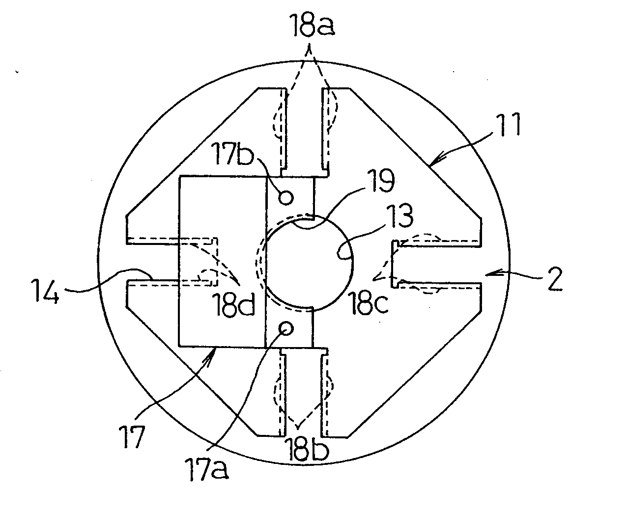
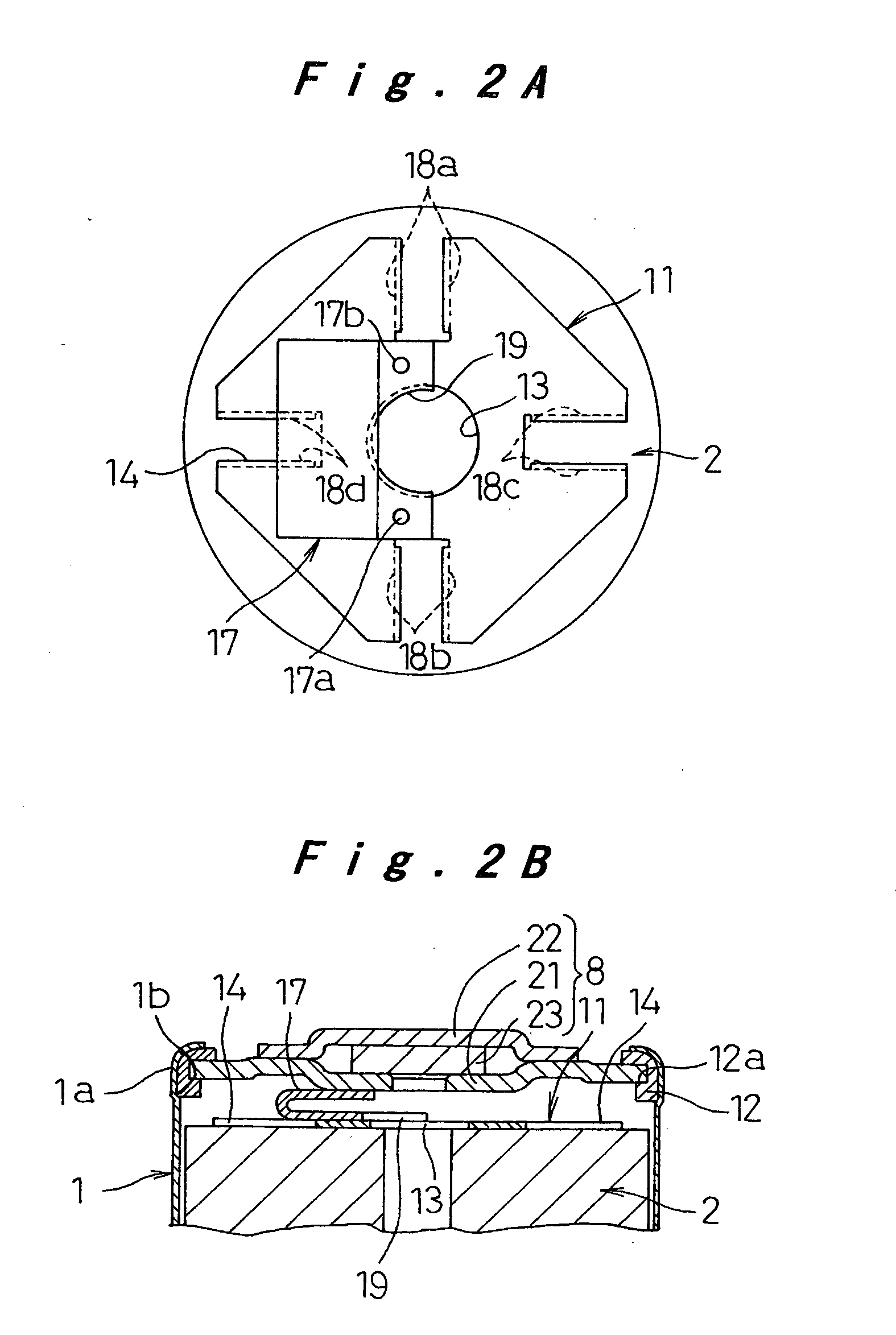
[0070]FIG. 5A is a plan view showing a relative arrangement of the electrode plate 2, the positive collector 11, and the positive lead 17 in the battery according to the present invention. FIG. 5B is a cross-sectional view corresponding to FIG. 5A. In FIGS. 5A and 5B, the components that are the same as or similar to those in FIGS. 2A and 2B are labeled with the same reference numerals and redundant description is omitted. Although the positive lead 17 shown in FIGS. 2A and 2B has the semi-circular notch 19, the positive lead 17 of the battery shown in FIGS. 5A and 5B has a circular hole 15 having a slightly smaller diameter than that of the electrolyte-injection hole 13 of the positive collector 11. Moreover, in the positive lead 17 of the present embodiment, four welded portions 16a through 16d for welding of the positive lead 17 to the positive collector 11 are provided at four positions surrounding the circular hole 15, respectively. In addition, a pressing piece 12b is formed i...

third embodiment

[0078] Next, the manufacturing process of the battery of the third embodiment will be described with reference to FIGS. 9A through 11B. FIG. 9A shows a relative arrangement of the respective components to be assembled. In the first process, as shown with an arrow in FIG. 9A, the negative collector 9 is brought into contact with the end 4a (see FIG. 6) of the negative electrode plate 4 of the electrode plate group 2 and is welded to the end 4a by resistance welding. In addition, the respective burring projections 18a through 18d of the positive collector 11 are brought into contact with the end 3a (see FIG. 6) of the positive electrode plate 3 of the electrode plate group 2 and are welded to the end 3a by resistance welding. Further, the connection base portion 20a of the positive lead 20 is positioned and arranged with respect to the positive collector 11 in accordance with the relative arrangement shown in FIG. 7A, and thereafter the positive lead 20 is welded at two portions to th...


PUM

PropertyMeasurementUnit
lengthaaaaaaaaaa
current pathsaaaaaaaaaa
projection lengthaaaaaaaaaa

Abstract

A battery having a collecting structure that can reduce internal resistance of the battery and a structure that allows easy manufacturing of the battery by the following processes is provided. An enlarged portion is formed near an opening end of a battery case and a supporting ledge is provided on the inner surface of the lower end of the enlarged portion. A collector of one polarity is bonded to an electrode plate group. A connection lead is bonded to the collector at one end and is bonded to a lower surface of a sealing member at the other end. An insulation gasket is mounted to a peripheral edge portion of the sealing member from a side opposite to the collector. The peripheral edge portion of the sealing member is supported by the supporting ledge with the insulation gasket interposed therebetween. Then, the peripheral edge portion of the sealing member is horizontally fastened and securely held via the insulation gasket by caulking the opening end of the battery case and performing a process for reducing the diameter of the enlarged portion.

Description

[0001] The present disclosure relates to subject matter contained in priority Japanese Patent Application Nos. 2003-304051, 2003-362872 and 2004-047469, filed on Aug. 28, 2003, Oct. 23, 2003 and Feb. 24, 2004, respectively, the contents of which is herein expressly incorporated by reference in its entirety. BACKGROUND OF THE INVENTION [0002] 1. Field of the Invention [0003] The present invention relates to a battery having a collecting structure and a sealing structure that are novel and allow increase of output and capacity, and a method for manufacturing such battery in a suitable manner. [0004] 2. Description of the Related Art [0005] In recent years, it has been advanced rapidly to make electronic devices such as audio-video equipment and a personal computer or mobile communication equipment portable and / or cordless. As a driving power source of these electronic devices, an aqueous battery such as a nickel-cadmium battery or nickel metal hydride battery was typically used conven...

Claims


Application Information

Patent Timeline
Patent Type & Authority Applications(United States)
IPC IPC(8): H01M6/10H01M10/04H01M10/05H01M10/052H01M10/0566H01M10/0587H01M10/28H01M50/119H01M50/167H01M50/171H01M50/184H01M50/186H01M50/533H01M50/536H01M50/538H01M50/627
CPCH01M2/022Y10T29/49114H01M2/027H01M2/0275H01M2/0285H01M2/0413H01M2/046H01M2/08H01M2/1229H01M2/22H01M2/263H01M2/361H01M10/0431H01M10/30H01M10/345Y02E60/122Y02E60/124Y10T29/49107Y10T29/49108H01M2/023Y02E60/10H01M50/56H01M50/107H01M50/545H01M50/152H01M50/171H01M50/325H01M50/528H01M50/538Y02P70/50H01M50/186H01M50/627H01M50/536H01M50/533H01M50/184H01M50/119H01M50/167
Inventor MIYAHISA, MASAHARUKASAHARA, HIDEKITADA, YOSHIYUKINIITSUMA, TOSHITAKA
Owner PANASONIC CORP
Why Eureka
Try Eureka