Electrochromic salts, solutions, and devices

a technology of electrolyte solution and electrolyte, applied in the direction of discharge tube luminescnet screen, non-aqueous electrolyte cells, instruments, etc., can solve the problems of limited solubility of molten salts, /sup> may be unstable, limited commercial electrochromic windows and mirrors,

Inactive Publication Date: 2005-07-14
TRIAD NAT SECURITY LLC
View PDF20 Cites 1 Cited by
  • Summary
  • Abstract
  • Description
  • Claims
  • Application Information

AI Technical Summary

Problems solved by technology

Commercially available electrochromic windows and mirrors are generally limited to operating temperatures above 0° C. The molten salts described above have a much wider potential window, sometimes greater than 5 Volts, and low glass transition temperatures (some as low as −80° C.) or melting points (some below −20° C).
ce). While the viologen salts described in these patents have reportedly been used in combination with molten salts to provide electrolyte solutions for electrochromic devices, at least some of the viologen salts, the dichloride salts or their electrochemically generated reduction products, for example, may have limited solubility in molten salts and / or tend to form precipit
ates. Anions such as BF4− and PF6− may be unstable after long periods of time, and ClO4− containing salts are known to be uns
table. These problems impede the performance of, and affect the lifetime of, the

Method used


Image

  • Electrochromic salts, solutions, and devices
  • Electrochromic salts, solutions, and devices
  • Electrochromic salts, solutions, and devices

Examples


example 1

[0167] Preparation of 1,1′-dimethyl-4,4′-dipyridinium bis(bis(trifluoromethylsulfonyl)imide) [15]. A first solution of 1,1′-dimethyl-4,4′-dipyridinium dichoride (1.128 g in 10 mL distilled H2O) was prepared. A second solution of lithium bis(trifluoromethylsulfonyl)imide (LiNTf2) (1.264 g in 10 mL distilled H2O) was prepared and slowly added via pipette to the first solution with stirring. Salt 15 formed as a white solid. The mixture was filtered, and the solid white powder MeV(NTf)2 formed. The solution was filtered and the solid was dissolved in acetone. The acetone was removed under a vacuum to produce 15 as a white powder.

example 2

[0168] Preparation of a solution of the radical cation of [15]. An electrolyte solution of about 0.011 g of 15 (prepared according to Example 1) in about 1.0 mL 1-butyl-3-methylimidazolium bis(trifluoromethylsulfonyl)imide was prepared under an inert atmosphere of helium. A chamber for the solution was provided by compressing a 0.5 inch diameter o-ring in between two 0.5-inch diameter conducting indium tin oxide (ITO) electrodes. The electrolyte solution was injected into the chamber through the o-ring.

[0169] The electrodes were connected to an HCH instruments Model 730A Electrochemical Analyzer. Bulk electrolysis of the solution at the reducing potential of −0.5V, which was indicated by the first peak of the cathodic wave, produced a blue color for the solution within about 5 seconds.

example 3

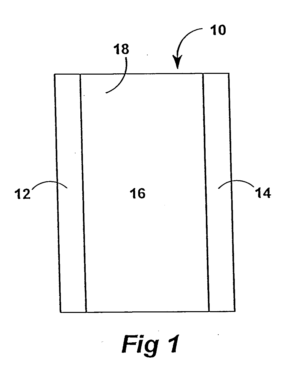
[0170] Preparation of an electrochromic window using [15]. An electrolyte solution of about 0.022 g of 15 and about 0.0050 g N,N,N,N-tetramethyl-p-phenylenediamine in about 2.0 mL 1-butyl-3-methylimidazolium bis(trifluoromethylsulfonyl)imide was prepared under an inert atmosphere of helium. A chamber for the solution was provided by compressing a 0.5 inch diameter o-ring in between two 0.5-inch diameter conducting indium tin oxide (ITO) electrodes. The solution was injected into the chamber through the o-ring to provide an electrochromic window.

[0171] The electrodes of the window were connected to an HCH instruments Model 730A Electrochemical Analyzer. Bulk electrolysis of the solution at the reducing potential of −0.5V (indicated by the first peak of the cathodic wave) produced a blue color within about 5 seconds.


PUM

PropertyMeasurementUnit
glass transition temperaturesaaaaaaaaaa
melting pointsaaaaaaaaaa

Abstract

Electrochromic salts. Electrochromic salts of dicationic viologens such as methyl viologen and benzyl viologen associated with anions selected from bis(trifluoromethylsulfonyl)imide, bis(perfluoroethylsulfonyl)imide, and tris(trifluoromethylsulfonyl)methide are produced by metathesis with the corresponding viologen dihalide. They are highly soluble in molten quarternary ammonium salts and together with a suitable reductant provide electrolyte solutions that are used in electrochromic windows.

Description

STATEMENT REGARDING FEDERAL RIGHTS [0001] This invention was made with government support under Contract No. W-7405-ENG-36 awarded by the U.S. Department of Energy. The government has certain rights in the invention.FIELD OF THE INVENTION [0002] The present invention relates generally to electrochromic salts and electrolyte solutions prepared using electrochromic salts for electrochromic devices such as electrochromic windows and variable reflectance mirrors. BACKGROUND OF THE INVENTION [0003] Electrochromism relates to the reversible color change induced in a material by an applied electric potential or current. Materials that exhibit electrochromism are used in electrochromic windows, variable reflectance mirrors, and other types of electrochromic devices. [0004] Electrochromic devices have been described, for example, in U.S. Pat. No. 3,451,741 to Manos; in U.S. Pat. No. 4,090,782 to Bredfeldt et al.; in U.S. Pat. No. 4,093,358 to Shattuck and Sincerbox; and in U.S. Pat. No. 4,13...

Claims


Application Information

Patent Timeline
Patent Type & Authority Applications(United States)
IPC IPC(8): C07DC07D401/04C07D471/02C07D471/04C07D487/04C07D487/14C09K9/02G02F1/1503G02F1/153H01G2/00H01G9/145H01G9/22H01J1/62H01J63/04H01M6/16
CPCC09K9/02C09K2211/1029C09K2211/1044C09K2211/1059Y02E60/13H01G9/145H01G9/22H01G11/02H01G11/62G02F1/1521G02F1/1503
Inventor BURRELL, ANTHONY K.WARNER, BENJAMIN P.MCCLESKY, T. MARK
Owner TRIAD NAT SECURITY LLC
Why Eureka
Try Eureka