
Electrically-based fluid corrosion/erosion protection apparatus and associated methods

a technology of corrosion/erosion protection and electric fluid, which is applied in the direction of liquid/fluent solid measurement, resistance/reactance/impedence, instruments, etc., can solve the problems of corresponding premature failure, increase in the corrosivity level of the fluid which they contain, and premature deterioration of the fluid system materials, etc., to facilitate the formation of corrosion gaps, prevent or at least substantially reduce the flow of electrical current through the sacrificial member, simple, inexpensive and reliable

Inactive Publication Date: 2005-07-14
RHEEM MFG CO
View PDF10 Cites 6 Cited by
  • Summary
  • Abstract
  • Description
  • Claims
  • Application Information

AI Technical Summary

Benefits of technology

[0008] The corrosion protection system of the present invention is of a simple, inexpensive and reliable construction in which the sacrificial member provides the dual functions of directly detecting an unacceptable chemical corrosivity level within the vessel and, via a corrosion-created prevention of electrical current flow therethrough, directly triggering the responsive corrosion detection signal.

Problems solved by technology

Fluid-containing vessels, such as tanks and the like, are often susceptible to internal chemical corrosion and / or mechanical erosion damage, and corresponding premature failure when the chemical corrosivity level of the fluid which they contain increases.
For example, water chemistry is known to attack boiler, water heater and chiller tank materials, with the result that the tanks, and associated fluid system materials, can prematurely deteriorate.
A primary disadvantage of many of these previously proposed corrosion detection systems has been their structural and / or fabricational complexity which undesirably increases their overall costs.

Method used


Image

  • Electrically-based fluid corrosion/erosion protection apparatus and associated methods
  • Electrically-based fluid corrosion/erosion protection apparatus and associated methods

Examples


Embodiment Construction

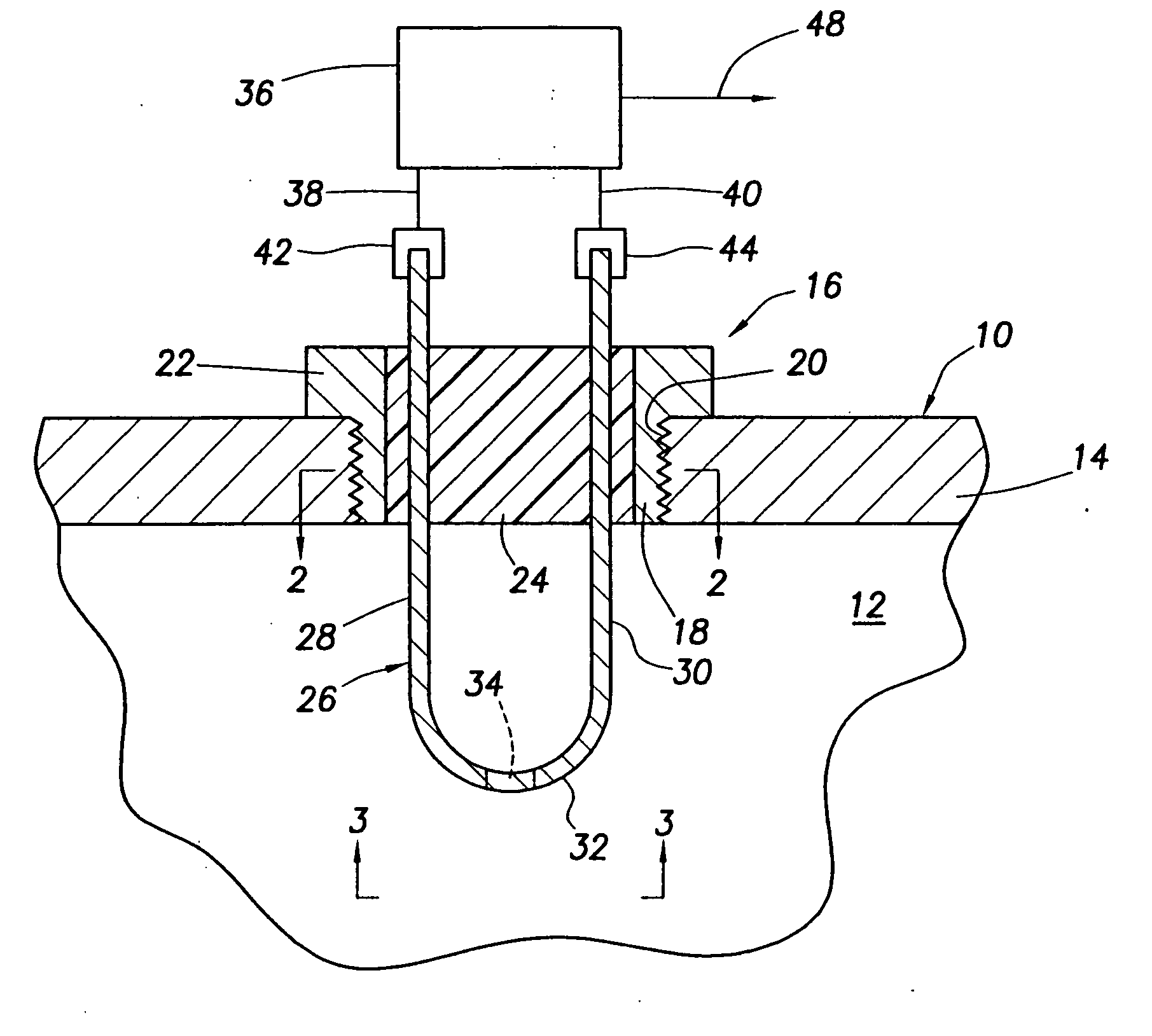
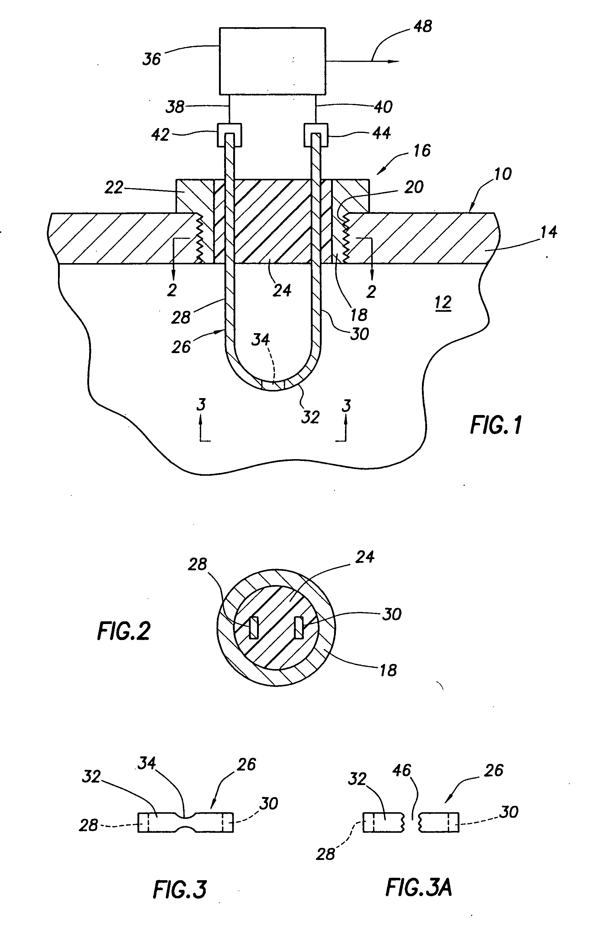
[0013] Schematically depicted in FIG. 1 is an illustrative vessel 10 adapted to hold a fluid 12, which may be pressurized or unpressurized, and having a chemically corrodable outer wall 14. The fluid 12 may be a liquid, such as water, or a gas, and the vessel 10 may representatively, but not by way of limitation, be a metal tank of the type used in water heaters, boilers, chillers or the like.

[0014] Operatively associated with the vessel 10, and embodying principles of the present invention, is specially designed protective apparatus 16 for protecting the vessel 10 against chemical corrosion and / or mechanical corrosion of the interior surface of its outer wall 14 by the fluid 12 within the vessel 10 in the event that the chemical corrosivity of the fluid 12 becomes undesirably high.

[0015] The protective apparatus 16 includes a generally tubular metal connection member 18 sealingly threaded into an opening 20 in the outer vessel wall 14 and having an outer flange portion 22. Sealin...


PUM

PropertyMeasurementUnit
chemical corrosionaaaaaaaaaa
mechanical erosionaaaaaaaaaa
chemical corrosivityaaaaaaaaaa

Abstract

The interior of a vessel containing fluid is protected against undesirable chemical corrosion and / or mechanical erosion caused by the fluid due, for example, to changes in the chemistry of the fluid, by an electrically conductive, chemically corrodable sacrificial member having an internal section disposed within the tank and an exposed exterior portion connected to an electrical corrosion / erosion detection circuit operative to create and maintain a flow of electrical current through the sacrificial member. When the internal section of the sacrificial member is subjected to a predetermined combination of fluid exposure time and fluid chemical corrosivity within the vessel a chemical corrosion gap is formed within the internal sacrificial member section. Creation of this gap terminates or at least substantially reduces electrical current flow through the sacrificial member and responsively causes the detection circuit to output a corrosion / erosion detection signal indicating the need for corrective action.

Description

BACKGROUND OF THE INVENTION [0001] The present invention generally relates to protecting fluid containing vessels from chemical corrosion and / or mechanical erosion by fluid disposed therein and, in an illustrated embodiment thereof, more particularly provides specially designed pressure-based chemical corrosion / mechanical erosion monitoring and protection apparatus and associated methods for such vessels. [0002] Fluid-containing vessels, such as tanks and the like, are often susceptible to internal chemical corrosion and / or mechanical erosion damage, and corresponding premature failure when the chemical corrosivity level of the fluid which they contain increases. For example, water chemistry is known to attack boiler, water heater and chiller tank materials, with the result that the tanks, and associated fluid system materials, can prematurely deteriorate. [0003] Various proposals have previously been made for monitoring corrosion of a sacrificial member disposed in fluid contained ...

Claims


Application Information

Patent Timeline
Patent Type & Authority Applications(United States)
IPC IPC(8): C23F13/00C23F13/22C23F15/00G01N17/02G01N27/00
CPCG01N17/02
Inventor TABER, BRUCE E.
Owner RHEEM MFG CO
Learn More