Raman laser with improved output power and lower sensitivity to the output coupler reflectivity

a laser and output coupler technology, applied in the field oframan lasers, can solve the problems of raman lasers with so many reflectors that are difficult to manufacture, and the strength and quality of transmitted optical signals decrease, and the effect of reducing the sensitivity of the output coupler reflectivity

Inactive Publication Date: 2005-07-14
ALCATEL LUCENT SAS
View PDF3 Cites 9 Cited by
  • Summary
  • Abstract
  • Description
  • Claims
  • Application Information

AI Technical Summary

Benefits of technology

[0009] This object is achieved in accordance with the invention by the use of a Raman laser with a particular optical resonant cavity for the electromagnetic radiation of wavelength at the Raman radiation λRR. Such resonant cavity is made out of an unpaired reflector rRR with a reflecting wavelength corresponding to said Raman radiation λRR. The second reflector at the output reflector needed to build an optical resonant cavity is advantageously defined by Rayleigh scattering to take place at least at a portion of the optical fiber between the reflector rRR and the output of that Raman laser. Such Rayleigh scattering results from random localised variations of the molecular positio

Problems solved by technology

Over such long distances, however, the strength and quality of a transmitted optical signal diminishes.
Not only is a Raman laser with so many reflectors difficult to manufacture since the two members of each pair of reflectors must have essentially the same center wavelength, but the unwanted attenuation due

Method used


Image

  • Raman laser with improved output power and lower sensitivity to the output coupler reflectivity
  • Raman laser with improved output power and lower sensitivity to the output coupler reflectivity
  • Raman laser with improved output power and lower sensitivity to the output coupler reflectivity

Examples


Embodiment Construction

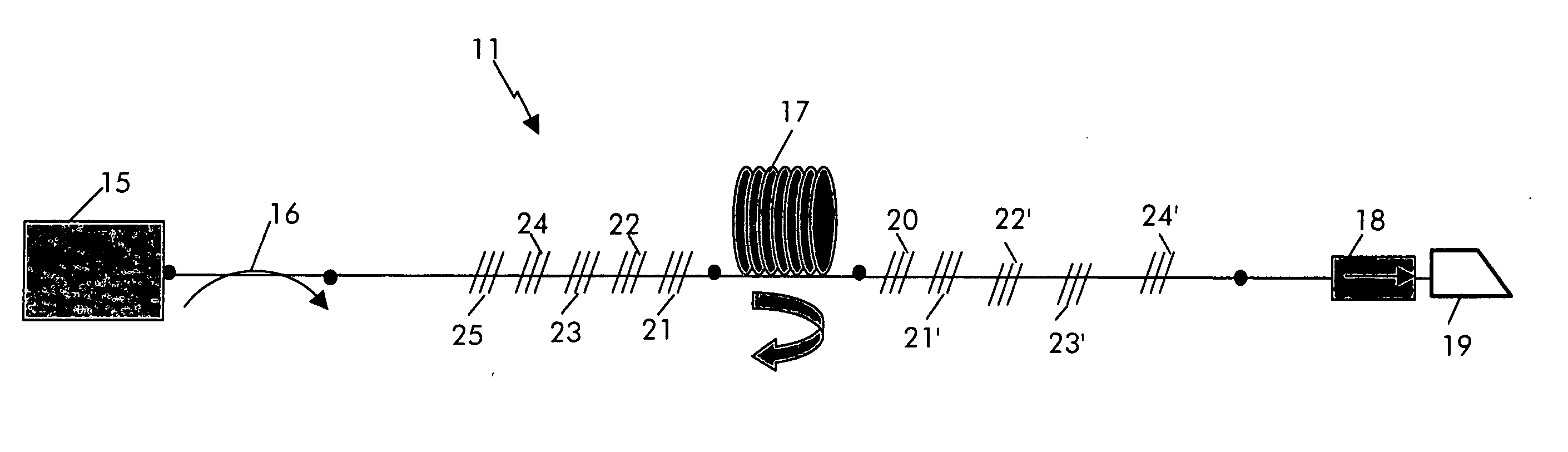
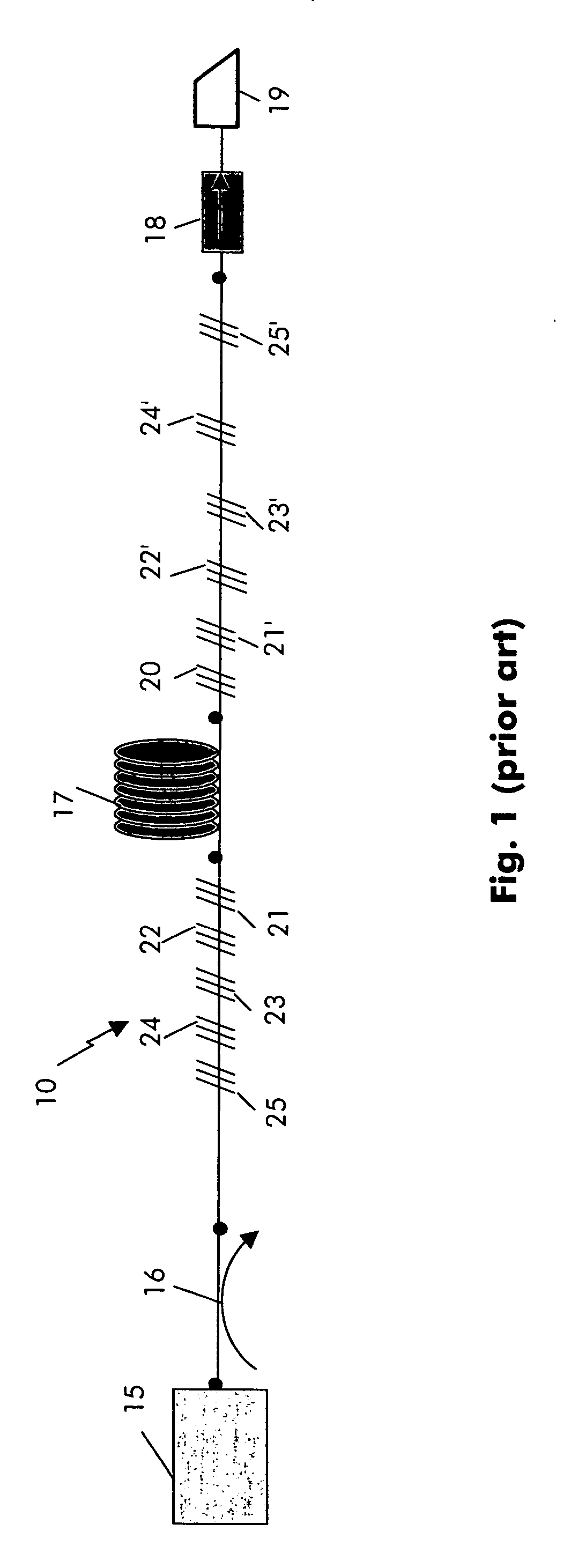
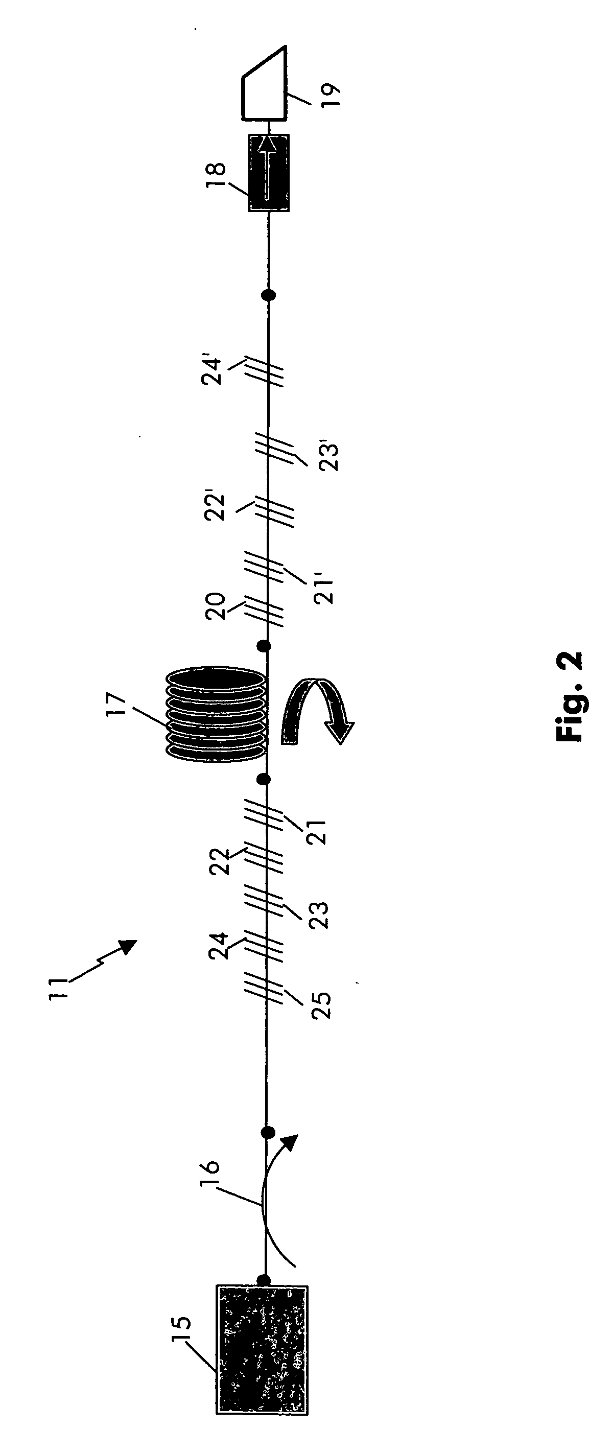
[0019]FIG. 2 shows a Raman laser 11 according to the invention. Such a Raman laser 11 comprises some lengths of optical fiber used as Raman fiber 17. That Raman fiber 17 is surrounded on both part by a number of reflectors (ri, r′i). At the present example described in FIG. 2 are five reflectors 21, 22, . . . , 25 on the input side of the Raman laser 11 and five reflectors 20, 21′, . . . , 24′ on its output side. All these reflectors 20, 21, 21′, . . . , 24, 24′, 25, are preferably made by some fiber Bragg gratings structured on said optical fiber. But other kind of reflectors could be conceivable.

[0020] The Raman laser 11 is coupled on its input side via a coupler 16 with a pump source 15. This pump source will provide initial pump radiation at wavelength λPO into the Raman laser 11. On the output side of the Raman laser 11 is put an isolator 18 to protect it from any radiation coming from outside via its output. That output is characterized by a tilled cleaved end face 19 such to...


PUM


Abstract

It is proposed to use a Raman laser with a new optical resonant cavity for the Roman radiation λRR. Such resonant cavity is made out of an unpaired reflector rRR with a reflecting wavelength corresponding to said Raman radiation λRR. The second reflector at the output needed to build an optical resonant cavity is advantageously defined by Rayleigh scattering to take place at least at a portion of the optical fiber between the reflector rRR and the output of that Raman laser. With the use of the Rayleigh scattering as a complementary reflector to be associated with the unpaired reflector, it is then possible to obtain an optical resonant cavity for the Raman radiation λRR with an output reflectivity of less than 1% i.e. with optimized Raman radiation. Such Raman laser is particularly appropriated to be used as a second order Raman laser.

Description

TECHNICAL FIELD [0001] The present invention relates to a Raman laser for the emission of Raman radiation and to an apparatus for Raman amplification comprising such Raman laser. Furthermore, it is related to a method for producing Raman radiation. The invention is based on a priority application EP 04 290 046.4 which is hereby incorporated by reference. BACKGROUND OF THE INVENTION [0002] Optical fiber technology is currently applied in communication systems to transfer information, e.g., voice signals and data signals, over a long distances as optical signals. Over such long distances, however, the strength and quality of a transmitted optical signal diminishes. Accordingly, techniques have been developed to regenerate or amplify optical signals as they propagate along an optical fiber. [0003] One well known amplifying technique exploits an effect called Raman scattering to amplify an incoming information bearing optical signal. Roman scattering describes the interaction of light w...

Claims


Application Information

Patent Timeline
IPC IPC(8): H01S3/30
CPCH01S3/0675H01S3/302H01S3/0809
Inventor LEPLINGARD, FLORENCEBORNE, SOPHIE
Owner ALCATEL LUCENT SAS
Why Eureka
Try Eureka