
Pressure relief system for paint circulation applications

Inactive Publication Date: 2005-07-14
DURR SYST INC
View PDF18 Cites 14 Cited by
  • Summary
  • Abstract
  • Description
  • Claims
  • Application Information

AI Technical Summary

Benefits of technology

[0008] A closed loop paint circulation system provides continuously circulating paint between a paint reservoir and a paint applicator for use in a production paint facility. A circulation line fluidly communicates the paint at a desired operational pressure between the paint reservoir and the paint applicator. A relief line is cooperably seperable from the circulation line by a relief device that opens for reducing the operational pressure of the paint circulating through the circulation line when the operational pressure increases beyond a predetermined value. A secondary pressure relief device is cooperable with the first pressure relief device where the second pressure relief device actuates in response to a d

Problems solved by technology

Due to the complex nature of most paint application facilities, wherein the paint booth is located, the reservoir is located a substantial distance from the paint applicator that atomizes and applies paint to the substrate of each vehicle body.
Each of these paints, and in particular, the spray primer surfacer and the base coat are necessarily maintained in continuous circulation to prevent the solids suspended in these paints from settling, which is known to cause paint defects that are visible in the painted products.
Furthermore, colored primer surfaces and base coats generally include high percentages of pigment which are known to settle when these paints are not maintained in continuous circulation.
For example, if the paint is prevented from circulating while the pump continues to operate pressure will build up in the paint line causing damage to various seals both inside and external to the pump, which again could cause paint to spill requiring a hazardous waste cleanup.
This is known to be a laborious and slow process which results in significant amounts of lost production through the paint application facility.

Method used


Image

  • Pressure relief system for paint circulation applications
  • Pressure relief system for paint circulation applications

Examples


Embodiment Construction

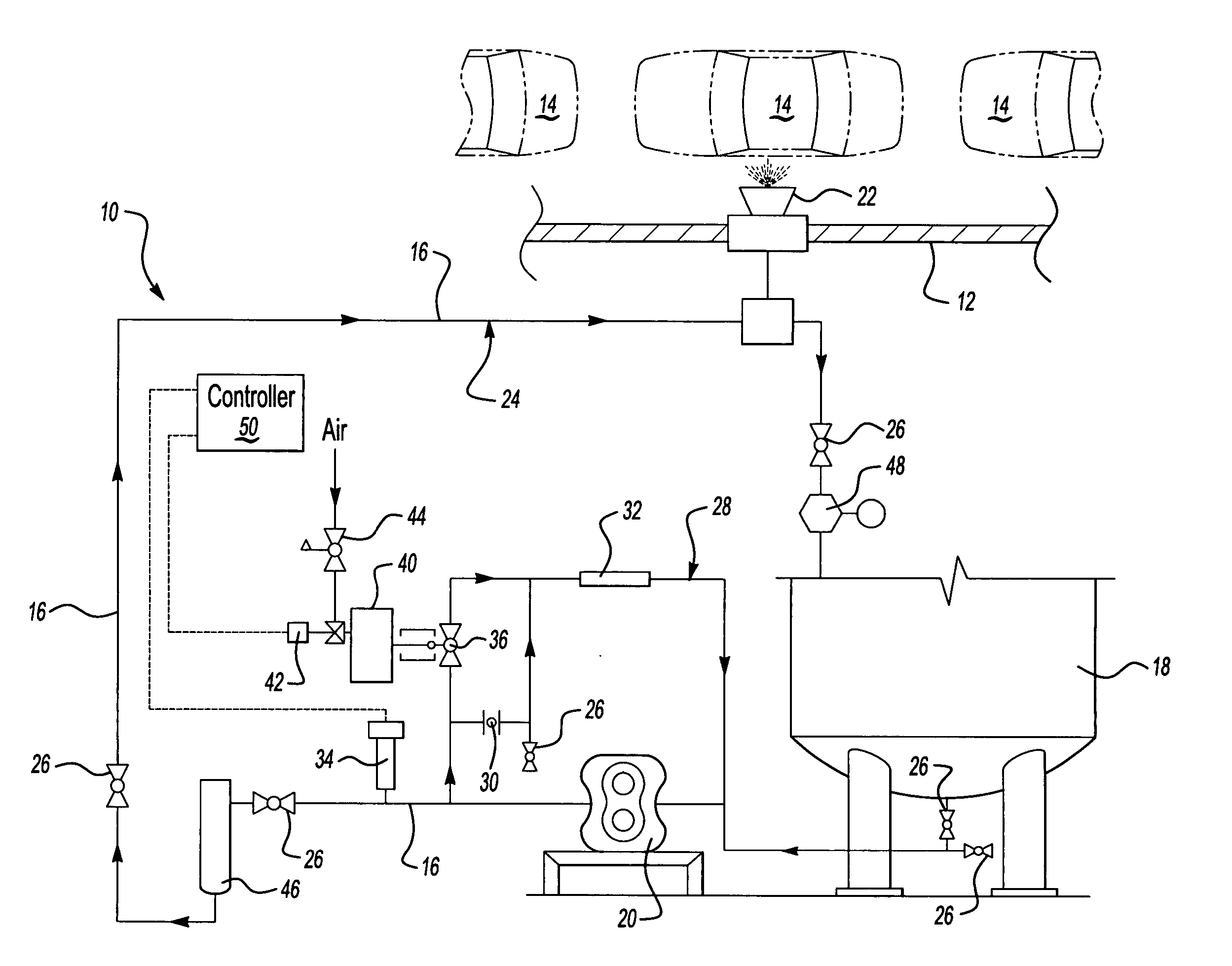
[0012] Referring to FIG. 1, wherein like numerals indicate like or corresponding parts, an inventive closed loop paint circulation system is generally shown at 10. The paint circulation system 10 supplies paint to at least one paint booth 12 where the paint is applied to a product, such as, for example, a vehicle body 14. In a typical automobile assembly plant paint is maintained in constant circulation through long circulation line 16 stretching between a paint reservoir 18 and one or more paint spray booths 12 by a pump 20. The vehicle body 14 is transported through the paint spray booth 12 by conveying equipment (not shown) where the paint is applied to the vehicle body 14 and subsequently cured in a paint oven (not shown) as is known to those skilled in the art. The paint may be applied by human operators or mechanically by automated equipment 22 such as rotary atomizers. The equipment 22 is generally disposed inside the walls of the paint booth 12 and is robotically operated, a...


PUM


Abstract

A paint circulation system (10) for automotive coating applications presents a paint supply source (18) and a pump (20) for pumping the paint. A circulation line (16) is fluidly communicated with the paint supply source (18) and circulates the paint at an operational pressure. A relief line (28) has a pressure relief device (30) adaptable for withstanding a predetermined pressure of the paint and to circulate the paint through the relief line (28) as the operational pressure exceeds the predetermined flow pressure. A pressure control mechanism is operatively communicated with the circulation line (16) and the relief line (28). The pressure control mechanism senses the operational pressure to continuously circulate the paint in the relief line (28) in response to a difference between the operational pressure and the predetermined pressure before the operational pressure exceeds the predetermined pressure thereby preventing the pressure relief device (30) from actuating.

Description

RELATED APPLICATION [0001] This application claims priority to and all the benefits of U.S. Provisional Patent Application Ser. No. 60 / 533,660 filed on Dec. 31, 2003.FIELD OF THE INVENTION [0002] This invention relates to paint circulation systems used in automotive industry, and in particular, to a pressure control device for a paint circulation system. BACKGROUND OF THE INVENTION [0003] A production paint application process where paint is applied to a substrate, such as, for example a vehicle body moving through a paint booth, requires paint to be transferred from a paint reservoir to a paint applicator disposed in the paint booth. Due to the complex nature of most paint application facilities, wherein the paint booth is located, the reservoir is located a substantial distance from the paint applicator that atomizes and applies paint to the substrate of each vehicle body. [0004] The layers of paint applied to each vehicle body generally include a spray primer surfacer, a spray ba...

Claims


Application Information

Patent Timeline
IPC IPC(8): F04B49/06
CPCF04B49/065
Inventor KAPRON, JAMES R.
Owner DURR SYST INC
Learn More