Polishing pad, polishing apparatus, and polishing method

a polishing apparatus and polishing pad technology, applied in the direction of grinding/polishing apparatus, grinding machines, manufacturing tools, etc., can solve the problems that the polishing pad as above-mentioned cannot solve the polishing apparatuses, and the production cost of the polishing pad is high, so as to reduce the surface of the polishing pad, prevent the increase of the polishing resistance, and facilitate the removal of work from the polishing pad.

Inactive Publication Date: 2005-07-14
SONY CORP
View PDF63 Cites 6 Cited by
  • Summary
  • Abstract
  • Description
  • Claims
  • Application Information

AI Technical Summary

Benefits of technology

[0024] In the second polishing pad, since the plurality of holes piercing through the polishing pad in the thickness direction are provided and part of the plurality of holes are composed of clots, the hermetic seal property of between the surface to be polished and the polishing pad surface is lowered due to the presence of the slots and a negative pressure is less liable to be generated there, in the same manner as in the case of the first polishing pad. Therefore, it is easy to remove the work from the polishing pad surface after completion of polishing. Further, since a plurality of holes other than the slots are provided, the polishing resistance is restrained from increasing. Furthermore, since grooves are not provided in the present polishing pad, unlike the related-art polishing pads, there is no possibility that a polishing liquid might flow out through grooves to the exterior of the polishing pad. The slots formed in the polishing pad according to the present invention reserve the polishing liquid therein, which makes it possible to reduce the amount of the polishing liquid used. In addition, since the plurality of holes inclusive of the slots which are formed in the polishing pad according to the present invention can be formed by a single punching operation, the polishing pad is lower in production cost than the polishing pads provided with grooves which are formed by cutting. Further, since the slots are so formed as to pierce through the polishing pad in the thickness direction, the slots are not lost even when the polishing pad is worn as polishing proceeds. Accordingly, the polishing pad according to the present invention can show a longer pad life, as compared with the polishing pads provided with grooves.
[0025] A polishing apparatus according to the present invention is a polishing apparatus which uses a polishing pad according to the present invention, whereby the production cost of the polishing pad can be lowered. Since a polishing pad according to the present invention is thus used, the operating cost of the polishing apparatus is lowered. Furthermore, since the polishing pad according to the present invention has a longer pad life than that of a related-art polishing pad provided with grooves, the frequency of replacement of the polishing pad is reduced.
[0026] A polishing method according to the present invention is a polishing method in which a polishing pad according to the present invention is used, whereby the production cost of the polishing pad can be lowered. Since a polishing pad according to the present invention is thus used, polishing cost is lowered. Furthermore, since the polishing pad according to the present invention has a longer pad life than that of a related-art polishing pad provided with grooves, the frequency of replacement of the polishing pad is reduced.

Problems solved by technology

The polishing pad according to the Related Art 3 has the drawback that the production cost thereof is high, since the grooves must be formed by cutting after the formation of the holes by punching.
The problems involved in the polishing pads as above-mentioned cannot be solved by the polishing apparatuses and polishing methods using the polishing pads described in the above-mentioned Related Arts.

Method used


Image

  • Polishing pad, polishing apparatus, and polishing method
  • Polishing pad, polishing apparatus, and polishing method
  • Polishing pad, polishing apparatus, and polishing method

Examples


first embodiment

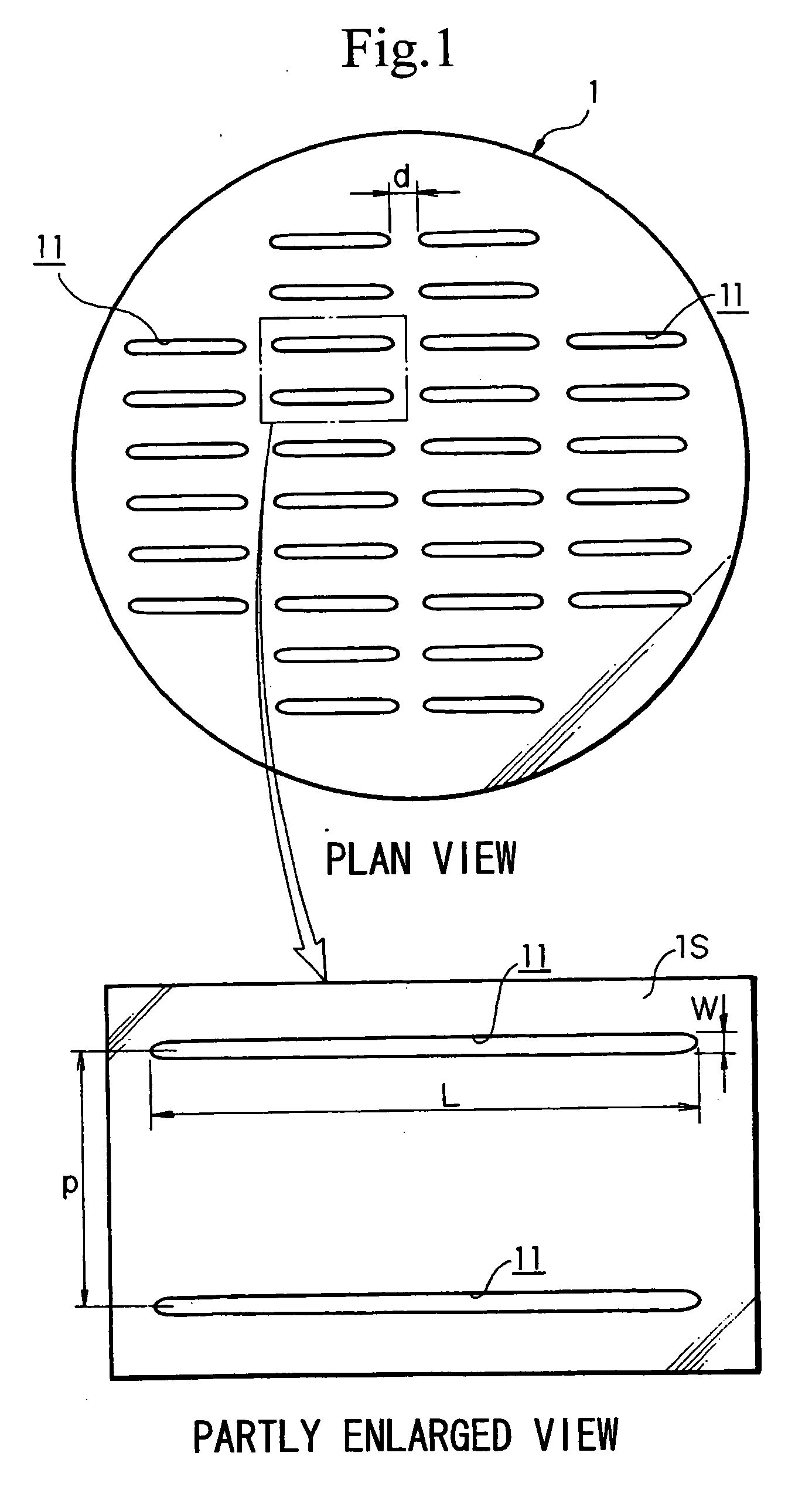
[0037] the first polishing pad according to the present invention will be described referring the plan view and the partly enlarged view shown in FIG. 1.

[0038] As shown in FIG. 1, the first polishing pad 1 is provided with a plurality of slots 11 piercing through the polishing pad 1 in the thickness direction, the slots 11 being aligned in the row direction and the column direction. The polishing pad 1 is formed of a resin, for example, foamed polyurethane or urethane. Its thickness is comparable to those of ordinary polishing pads, and is, for example, about 0.5 to 3.0 mm. The slots 11 are so formed as to be included in the polishing pad 1, and their length L in the longitudinal direction is not less than 20 mm. In addition, the slots 11 are formed at a pitch p which is not less than twice the length in the transverse direction (hereinafter referred to as the width) W thereof and is less than 100 mm. Incidentally, the spacing d in the longitudinal direction of the slots 11 is appro...


PUM

PropertyMeasurementUnit
lengthaaaaaaaaaa
lengthaaaaaaaaaa
widthaaaaaaaaaa

Abstract

A polishing pad which ensures that a work can be easily removed from the polishing pad surface after polishing, the amount of a polishing liquid used for polishing can be reduced, and the production cost of the polishing pad can be lowered. A first polishing pad (1) for polishing a work is provided with a plurality of slots (11) piercing the first polishing pad (1) in a sa direction, the length in the longitudinal direction of the slots (11) being preferably not less than 20 mm, the pitch in the width direction of the slots (11) being preferably less than 100 mm, and small holes (not shown) may be provided in addition to the slots (11).

Description

TECHNICAL FIELD [0001] The present invention relates to a polishing pad, a polishing apparatus and a polishing method, and particularly to a polishing pad provided with a plurality of slots, a polishing apparatus using the polishing pad, and a polishing method using the polishing pad. BACKGROUND ART [0002] As Related Art 1, there have been commercialized polishing pads which are provided grooves in the surface thereof. For example, there is available the polishing pad IC1000-A22 produced by Rodel Nitta Company. As shown in FIG. 9, this polishing pad 61 is provided in its polishing pad surface 61S with grooves 62, 2 mm in width, in a lattice pattern at a pitch of about 2 cm. Incidentally, the grooves 62 are omitted in the plan view. [0003] As Related Art 2, there have been commercialized polishing pads provided with a plurality of small holes (for example, small holes of 1.8 mm in diameter) in the surface thereof. One example known of this type of polishing pads is the polishing pad ...

Claims


Application Information

Patent Timeline
Patent Type & Authority Applications(United States)
IPC IPC(8): B24B37/20B24B37/26H01L21/304
CPCB24B37/26H01L21/304
Inventor SHIBUKI, SHUNICHI
Owner SONY CORP
Why Eureka
Try Eureka