
Dort process-based method and system for adaptive beamforming in estimating the aberration in a medium

a process-based method and system-based technology, applied in the field of distortion process-based method and system-based adaptive beamforming in estimating the aberration in a medium, can solve the problems of preventing the proper focusing degrading the image resulting from the aberrated wave front, and aberration of the wave front, so as to achieve better-focused images

Inactive Publication Date: 2005-07-14
KONINKLIJKE PHILIPS ELECTRONICS NV
View PDF7 Cites 24 Cited by
  • Summary
  • Abstract
  • Description
  • Claims
  • Application Information

AI Technical Summary

Benefits of technology

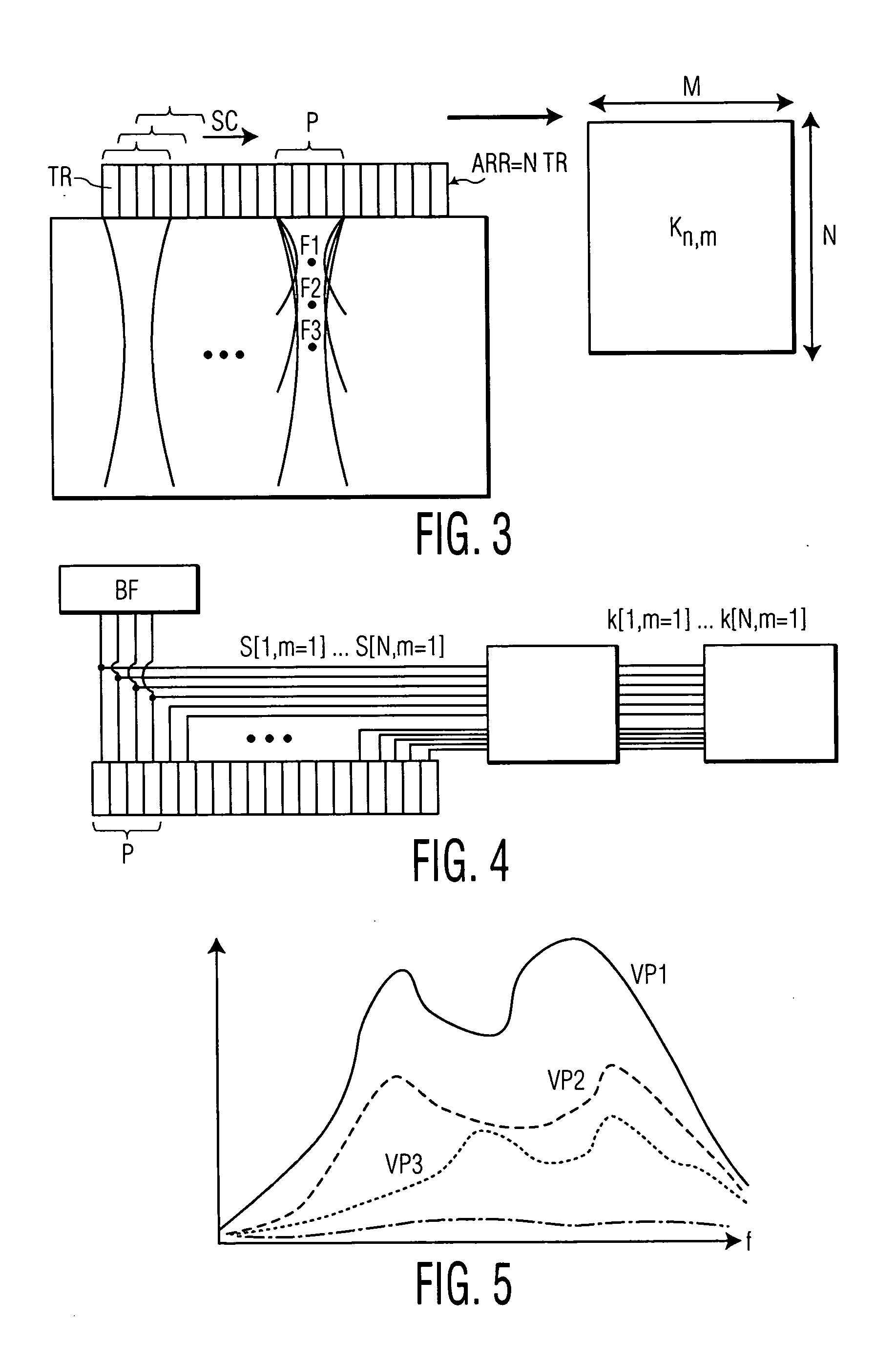
[0009] A technical advantage of the present invention is the ability to perform phase aberration correction. If there were no aberration present, then the delays would be determined by the geometry of the transducer and would form a parabola. This simple parabolic delay law is currently used in nonadaptive imaging to focus the received signals. If an aberration is present, then the focal law required to focus on the target will not be parabolic. The difference between the delay law found from the K matrix and the parabolic delay law is therefore an estimate of the aberration profile. The aberration estimate can be used to correct the global image beamforming delay table.
[0010] Another technical advantage of the present invention is the ability to achieve a speed of sound correction in which the focalization laws for several structures in the medium are processed to estimate the global speed of sound in the medium. The new global speed of sound could then be used to recalculate the delay tables used in beamforming and produce better-focused images of the medium.
[0011] Still another technical advantage of the present invention is the ability to provide image stabilization. For surgical procedures the algorithm could be initialized on a cell centered on the catheter. Once the focalization law corresponding to the catheter had been identified, the region could be imaged using focal laws centered on it. The aim of this would be to generate a clearer, better-focused image of the catheter.
[0012] Other objects, features and advantages of the invention will be apparent from the following specification taken in conjunction with the following drawings.

Problems solved by technology

These variations in sound speed aberrate the wave fronts and prevent them from properly focusing.
The image resulting from these aberrated wave fronts is degraded, exhibiting poor spatial and contrast resolution.
However, when there are multiple close scatterers, their wave fronts will interfere with one another and a wave front-following process will not yield an accurate estimate of the aberrator.
This process, like other known methods for the detection of small-size defects in medical ultrasonic imaging have the drawback of requiring many excitations particular to the method.
In addition, these particular excitations cannot be carried out by a common ultrasonic imaging apparatus and the use of a specific apparatus is therefore obligatory.

Method used


Image

  • Dort process-based method and system for adaptive beamforming in estimating the aberration in a medium
  • Dort process-based method and system for adaptive beamforming in estimating the aberration in a medium
  • Dort process-based method and system for adaptive beamforming in estimating the aberration in a medium

Examples


Embodiment Construction

[0023] The description which follows is presented so as to enable a person skilled in the art to implement and make use of the invention. Various alternatives to the preferred embodiment will be obvious to a person skilled in the art and the generic principles of the invention disclosed here may be applied to other embodiments. Thus the present invention is not deemed to be limited to the embodiment described, but rather to have the widest scope in accordance with the principles and characteristics described below.

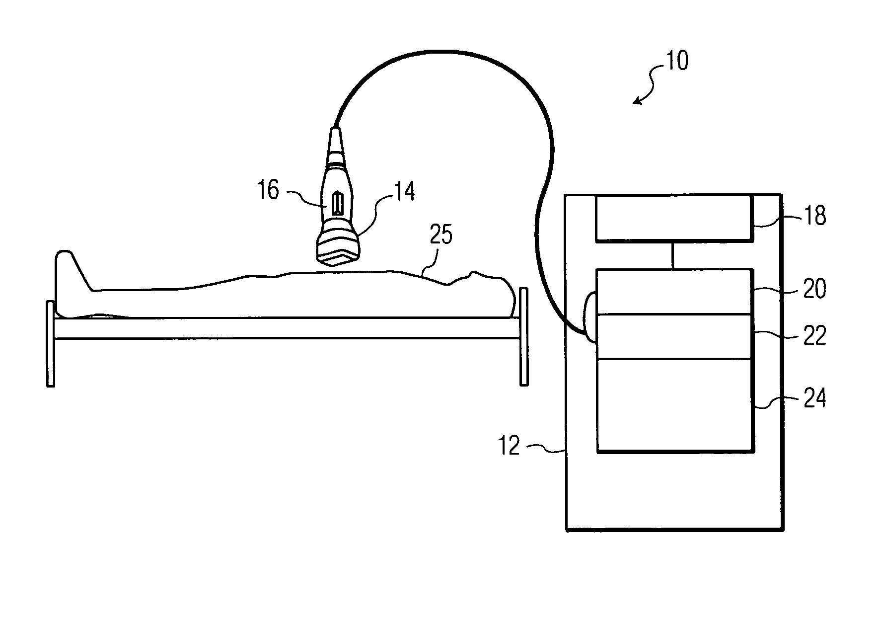
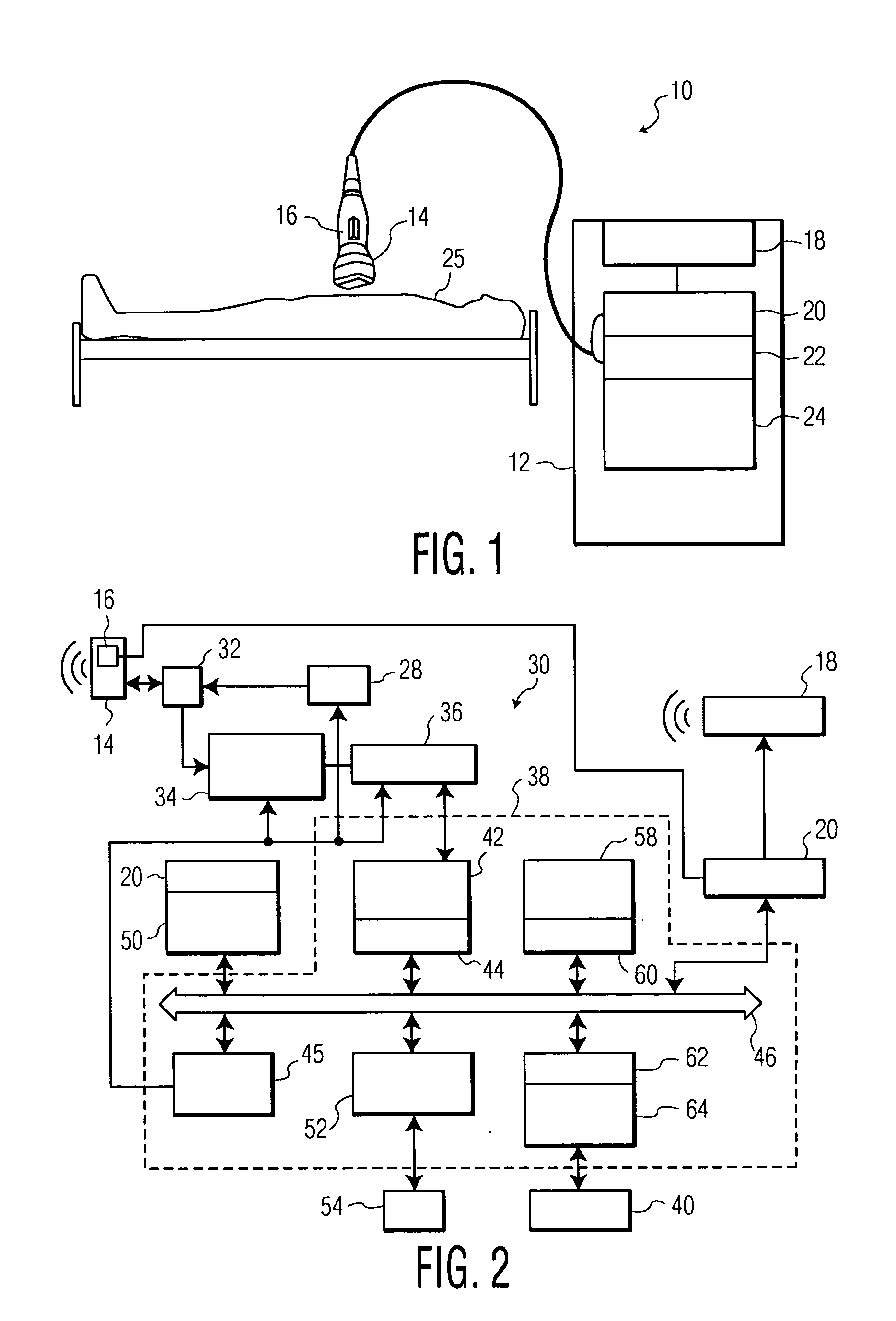
[0024]FIG. 1 shows a simplified block diagram of an ultrasound imaging system 10 that may be used in the implementation of the methodologies disclosed herein. It will be appreciated by those of ordinary skill in the relevant arts that ultrasound imaging system 10, as illustrated in FIG. 1, and the operation thereof as described hereinafter, is intended to be generally representative of such systems and that any particular system may differ significantly from that shown in...


PUM


Abstract

A method and system for adapting a focused beam of focused ultrasound imaging signals from an ultrasound probe (14) for compensating for the presence of an aberration (X) in a medium (OBJ) transmits a focused ultrasound imaging signal (FOC) into a region of a medium using a plurality of focused beams from a plurality of probe array elements (P). The return focused ultrasound imaging signals are received and a focused decomposition of time-reversal operator process determines the presence of an aberration in the region and correlates the aberration to selected probe array elements. The method and system adapt selected characteristics associated with the transmission of the ultrasound imaging signals and reception of the return focused ultrasound imaging signals from the selected probe array elements for compensating for the presence of the aberration in the region. The method and system further involve transmitting adapted focused ultrasound imaging signals into the region for generating a homogeneous wave front having reduced inhomogeneities arising from the aberration.

Description

BACKGROUND OF THE INVENTION [0001] The invention relates to a method for analyzing an organic medium potentially including defects within a noisy structure, the medium being excited by an ultrasonic signal emitted by a set of transducers. More particularly, the present invention relates a DORT process-based method and system for adaptive beamforming that estimates an aberration in a medium, as may be particularly applied to medical and ultrasonic imaging systems. [0002] In medical ultrasound imaging, focusing beams allows their transmission and receipt along multiple distinct lines to form an image. This focusing assumes a uniform sound speed within the medium. In reality, however, ultrasonic waves propagate through different tissue types with different speeds. These variations in sound speed aberrate the wave fronts and prevent them from properly focusing. The image resulting from these aberrated wave fronts is degraded, exhibiting poor spatial and contrast resolution. [0003] A num...

Claims


Application Information

Patent Timeline
Patent Type & Authority Applications(United States)
IPC IPC(8): A61B8/00G01S7/52G01S15/89
CPCA61B8/00G01S15/8977G01S7/52049
Inventor BURCHER, MICHAELFERNANDEZ, ANNA T.COHEN-BACRIE, CLAUDE
Owner KONINKLIJKE PHILIPS ELECTRONICS NV
Learn More