Catheter shaft having distal support

a technology of distal support and catheter shaft, which is applied in the field of medical devices, can solve the problems of balloon prolapse, significantly higher strain over the distal section, and low strain that is under the elastic limit of many materials common to this application, and achieves the effect of improving pushability and column strength

Active Publication Date: 2005-07-14
BOSTON SCI SCIMED INC
View PDF35 Cites 56 Cited by
  • Summary
  • Abstract
  • Description
  • Claims
  • Application Information

AI Technical Summary

Benefits of technology

[0009] One example embodiment pertains to a single-operator-exchange balloon catheter. The distal portion of the device has an inner tubular member, an outer tubular member and a balloon. The inner tube extends through the balloon. The distal end of the balloon is sealed to the inner tubular member, and the proximal end of the balloon is sealed to the outer tubular member. A reinforcing sleeve is slidably disposed over the inner tubular member and is attached to the outer tubular member at a distal connection point. The attachment may include a tie material. In one preferred embodiment, the reinforcing sleeve extends proximally to the distal connection point and distally into the balloon inflation cavity. Alternatively, the reinforcing sleeve may extend to near the distal end of the balloon, and may extend further proximally. In another alternative embodiment, the reinforcing sleeve extends to the balloon tip. A single bond area including the inner shaft, reinforcing sleeve and distal balloon waist can then be utilized to improve pushability and column strength.

Problems solved by technology

This may cause the inner tubular member and the balloon to prolapse within the outer tubular member.
If the inner tubular member is not attached at the proximal end of the balloon, the entire length of the inner tubular member can accommodate this growth, resulting in a low strain that is under the elastic limit of many materials common to this application.
This results in a significantly higher strain over this distal section, and this strain may be over the elastic limit of many of the materials used in this application.

Method used


Image

  • Catheter shaft having distal support
  • Catheter shaft having distal support
  • Catheter shaft having distal support

Examples


Embodiment Construction

[0018] The following description should be read with reference to the drawings wherein like reference numerals indicate like elements throughout the several views. The drawings, which are not necessarily to scale, depict illustrative embodiments of the claimed invention.

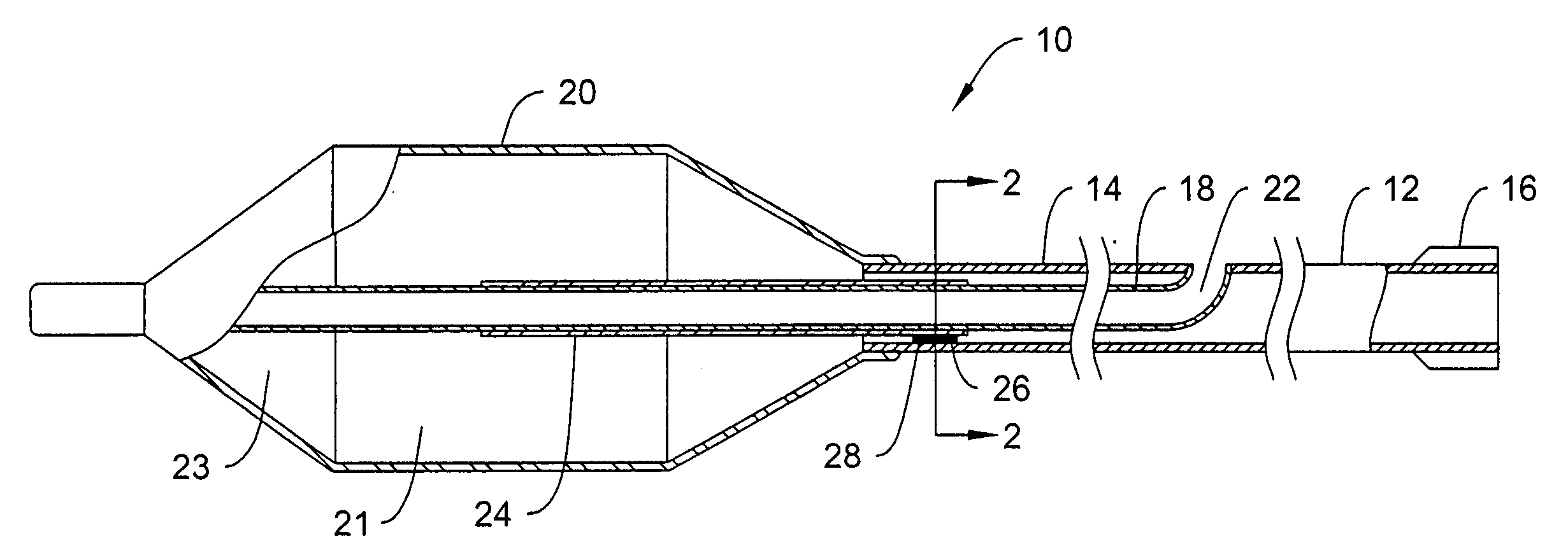
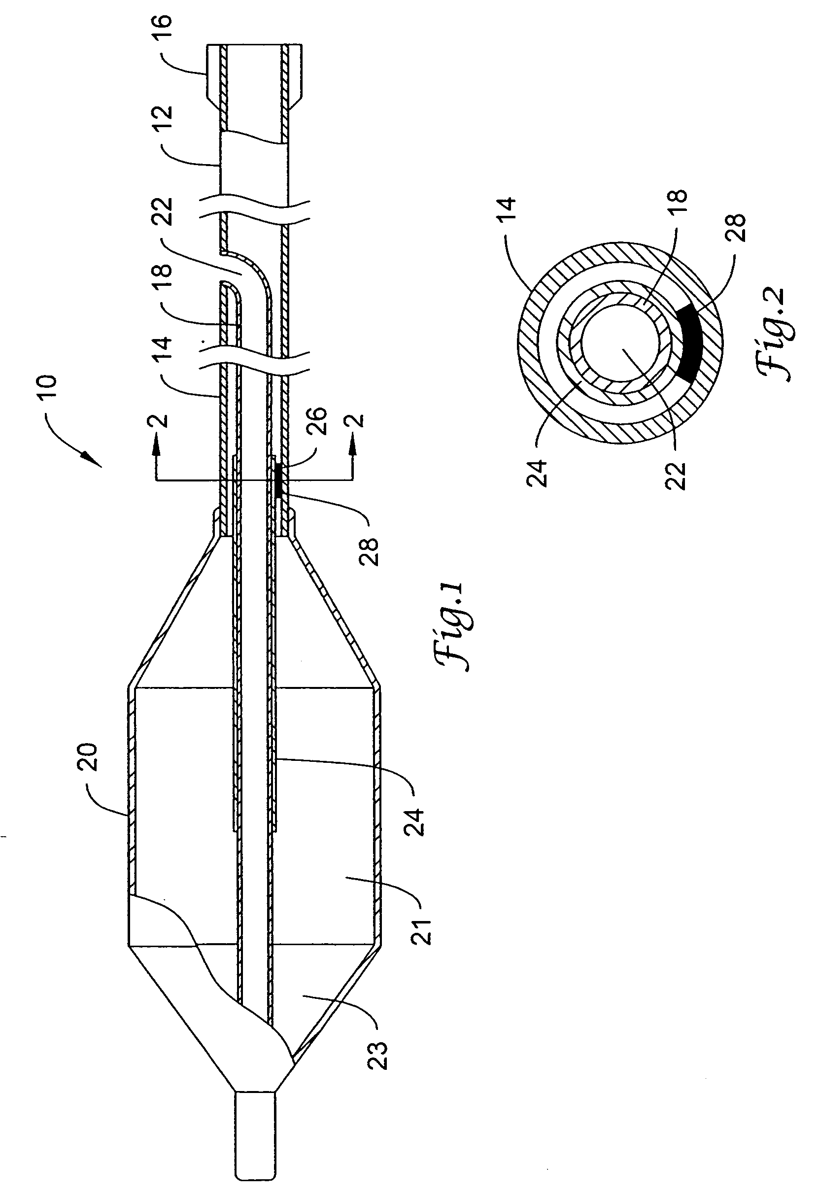
[0019]FIG. 1 is a partial plan view with portions in cross-section of an example single-operator-exchange balloon catheter 10 having a proximal end 12 with an outer tubular lo member 14 and a proximal hub assembly 16. Balloon catheter 10 may be used for an angioplasty procedure, a stent delivery procedure, or other therapeutic technique. An inner tubular member 18 is introduced through a wall of outer tubular member 14 and extends distally past a balloon 20. Outer tubular member 14 may terminate distally proximate the proximal end of balloon 20, and the proximal end of balloon 20 may be sealed to outer tubular member 14. The distal end of balloon 20 may be sealed to inner tubular member 18. A lumen 22 of inner tubul...


PUM


Abstract

A catheter comprising an inflatable balloon having a proximal end, a distal end, and an inflation cavity therebetween, a catheter shaft having the inflatable balloon affixed proximate a distal end thereof, the catheter shaft having an inflation lumen fluidly connected to the balloon inflation cavity. A guidewire lumen extends through the balloon cavity within a tubular member which is affixed to the inflatable balloon proximate the distal end. A reinforcing sleeve, having a proximal portion and a distal portion with a lumen extending therethrough, wherein the distal portion of the sleeve extends into the inflation cavity with at least a portion of the tubular member slidably disposed through the lumen thereof and the proximal portion is fixed relative to the catheter shaft and disposed in the catheter shaft inflation lumen.

Description

FIELD OF INVENTION [0001] This invention relates generally to medical devices including balloon catheters. More specifically, the present invention relates to an improved shaft design for an angioplasty or stent delivery catheter. BACKGROUND OF THE INVENTION [0002] In angioplasty, a balloon catheter is generally inserted into a patient's vasculature percutaneously, usually into a femoral or radial artery. The balloon is then advanced until it reaches the treatment site, at which there is usually a stenosis or other occlusion, and expanded to compress or displace the stenosis and improve the flow of blood. In some procedures, the expandable balloon can carry a stent to be expanded at the occlusion site. [0003] To efficiently and accurately advance a balloon catheter to a treatment site, guide catheters and guidewires are often positioned first. A balloon catheter may then be advanced over a guidewire and through a guide catheter. Consequently, a typical balloon catheter is constructe...

Claims


Application Information

Patent Timeline
Patent Type & Authority Applications(United States)
IPC IPC(8): A61F2/958A61M29/02
CPCA61M25/1006A61M25/1025A61M2025/0183A61M2025/0004A61M2025/0063A61M25/104
Inventor PERREAULT, DANIELDEVENS, DOUGLAS A. JR.
Owner BOSTON SCI SCIMED INC
Why Eureka
Try Eureka