Balloon assisted endoluminal prosthesis deployment

a technology of endoluminal prosthesis and balloon, which is applied in the field of balloon assisted endoluminal prosthesis deployment, can solve the problems of large lateral stiffness, high morbidity and mortality rate of procedures to treat aortic aneurysms, and generally regarded as involving higher risk and more difficulty, and achieves sufficient column strength

Pending Publication Date: 2020-07-09
TRIVASCULAR2
View PDF1 Cites 1 Cited by
  • Summary
  • Abstract
  • Description
  • Claims
  • Application Information

AI Technical Summary

Benefits of technology

[0007]Some embodiments of a delivery system for treatment of a vascular defect may include an endoluminal prosthesis for treatment of the vascular defect and a delivery catheter. The endoluminal prosthesis may include a tubular main graft portion with a thin flexible material, a main inner lumen, a proximal end and a distal end. The endoluminal prosthesis may also have a self-expanding anchor member that has a proximal portion and a distal portion. A distal end of the distal portion may be secured to a proximal end of the tubular main graft portion and a distal end of the proximal portion may be secured to a proximal end of the distal portion. In addition, the endoluminal prosthesis may also have a plurality of radiopaque markers which are circumferentially disposed adjacent the proximal end of the tubular main graft portion. For some embodiments, the delivery catheter of the delivery system may include an elongate shaft with sufficient column strength for percutaneous advancement within a patient's vasculature, the elongate shaft also having a proximal section and a distal section. A plurality of releasable belts may be disposed on the proximal section of the elongate shaft and configured to releasably constrain the self-expanding anchor member of the endoluminal prosthesis. A plurality of elongate release members may be disposed in operative communication with a distal end of the elongate shaft and said elongate release members may each include a proximal section configured to releasably secure at least one respective releasable belt while said releasable belt is in a configuration that constrains at least a portion of the self-expanding anchor member of the endoluminal prosthesis. An inflatable balloon may be secured to the elongate shaft within the main inner lumen of the tubular main graft portion of the endoluminal prosthesis. In some instances, the inflatable balloon may be disposed in an axial position wherein a proximal end of an inflatable section of the inflatable balloon is positioned adjacent but distal of the self-expanding anchor member. In some instances, the inflatable balloon may be disposed in an axial position wherein a proximal end of an inflatable section of the inflatable balloon is positioned adjacent but distal of the radiopaque markers. For some inflatable balloon embodiments, a proximal neck portion (a portion of a tubular member of the inflatable balloon tube which is in contact with an outer surface of the shaft) of some inflatable balloon embodiments may be positioned proximal the radiopaque markers so long as the proximal angled portion or proximal cone of the inflatable balloon and any pleats of the inflatable balloon material are disposed distal to the radiopaque markers.
[0008]Some embodiments of a method of deploying an endoluminal prosthesis may include advancing a delivery system into a patient's vasculature which includes an elongate shaft and an endoluminal prosthesis releasably secured to the elongate shaft. The method may also include releasing an outer constraint from a main graft portion of the endoluminal prosthesis and partially releasing an outer radial constraint from a self-expanding anchor member of the endoluminal prosthesis to allow the self-expanding anchor member to partially deploy. Thereafter, an inflatable balloon may be inflated and radially expanded so as to radially expand a portion of a graft portion of the endoluminal prosthesis which is disposed adjacent and axially coextensive with the inflatable balloon. In some cases, the inflatable balloon may be disposed within a main inner lumen of the main graft portion of the endoluminal prosthesis with a proximal end of an inflatable section of the inflatable balloon being disposed adjacent but distal of the self-expanding anchor member. In some cases, the inflatable balloon may be disposed within a main inner lumen of the main graft portion of the endoluminal prosthesis with a proximal end of an inflatable section of the inflatable balloon being disposed adjacent but distal of a plurality of radiopaque markers which may be circumferentially disposed adjacent a proximal edge of the main graft portion of the endoluminal prosthesis. An outer radial constraint on the self-expanding anchor member may then be fully released so as to fully deploying the self-expanding anchor member of the endoluminal prosthesis. In some cases, inflating and radially expanding the inflatable balloon may include inflating and radially expanding the inflatable balloon so as to apply an outward radial force onto an inner surface of a main inner lumen of the main graft portion of the endoluminal prosthesis until an outer surface of the main graft portion adjacent the inflatable balloon is urged into contact with an inner surface of the patient's vasculature.
[0009]Some embodiments of a delivery system for treatment of a vascular defect may include an endoluminal prosthesis for treatment of the vascular defect including and a delivery catheter. The endoluminal prosthesis may include a tubular main graft portion having a thin flexible material, a main inner lumen, a proximal end and a distal end. The endoluminal prosthesis may also include a self-expanding anchor member with a distal end thereof being secured to the proximal end of the tubular main graft portion. The delivery catheter may include an elongate shaft having a distal section and a proximal section, the proximal section being configured to releasably secure the endoluminal prosthesis in a constrained state. The delivery catheter may also include an inflatable balloon secured to the elongate shaft and disposed within the main inner lumen of the tubular main graft portion of the endoluminal prosthesis in an axial position wherein a proximal end of an inflatable section of the inflatable balloon is disposed adjacent but distal of the self-expanding anchor member.

Problems solved by technology

Surgical procedures to treat aortic aneurysms can have relatively high morbidity and mortality rates due to the risk factors inherent to surgical repair of this disease as well as long hospital stays and painful recoveries.
This is especially true for surgical repair of TAAs, which is generally regarded as involving higher risk and more difficulty when compared to surgical repair of AAAs.
Also, such existing systems have greater than desired lateral stiffness, which can complicate the delivery process, particularly for use in treatment of vascular defect sites that include a high degree of curvature or angulation.
Even with more flexible low profile delivery systems, deployment of endovascular prostheses in highly angulated and curved vessels may be problematic due to difficulties with visualization or imaging of the orientation of the prostheses during the deployment process.
Achieving a proper seal between an outer surface of an endovascular prosthesis and an inner surface of a vessel being treated after deployment of the endovascular prosthesis may also be challenging in some instances.
As such, minimally invasive endovascular treatment of aneurysms may not be available for many patients that would benefit from such a procedure and can be more difficult to carry out for those patients for whom the procedure is indicated.

Method used


Image

  • Balloon assisted endoluminal prosthesis deployment
  • Balloon assisted endoluminal prosthesis deployment
  • Balloon assisted endoluminal prosthesis deployment

Examples


embodiment 10

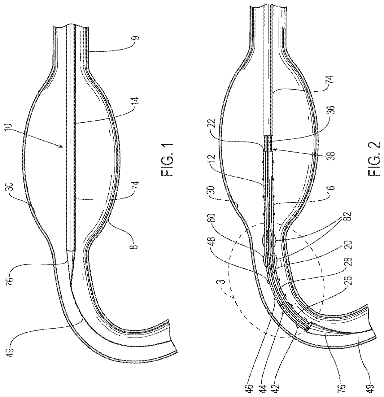
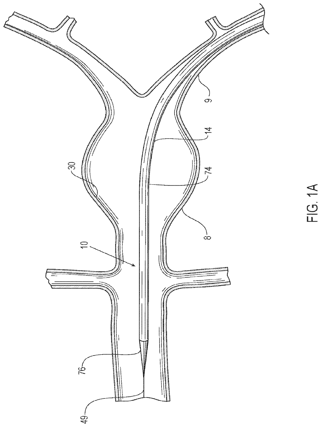
[0049]Referring to the figures, an embodiment of a delivery system 10 for treatment of a vascular defect such as aneurysm 8 is shown in FIGS. 1-12. Although the exemplary aneurysm 8 shown in the patient's vasculature 9 is a thoracic type aortic aneurysm, devices and methods as discussed herein and illustrated in the corresponding figures may also be used for any other suitable type of vascular defect such as abdominal aortic aneurysms (shown in FIG. 1A) and the like. The delivery system embodiment 10 may include an endoluminal prosthesis 12 for treatment of the vascular defect 8 and a delivery catheter 14. The endoluminal prosthesis may include a tubular main graft portion 16 made from a thin flexible material, and including a main inner lumen 18, a proximal end 20 and a distal end 22. The graft body may be formed from a flexible and supple graft material, such as PTFE, and have a main fluid flow lumen disposed in a main graft portion therein. For some embodiments, flexible graft ma...

embodiment 24

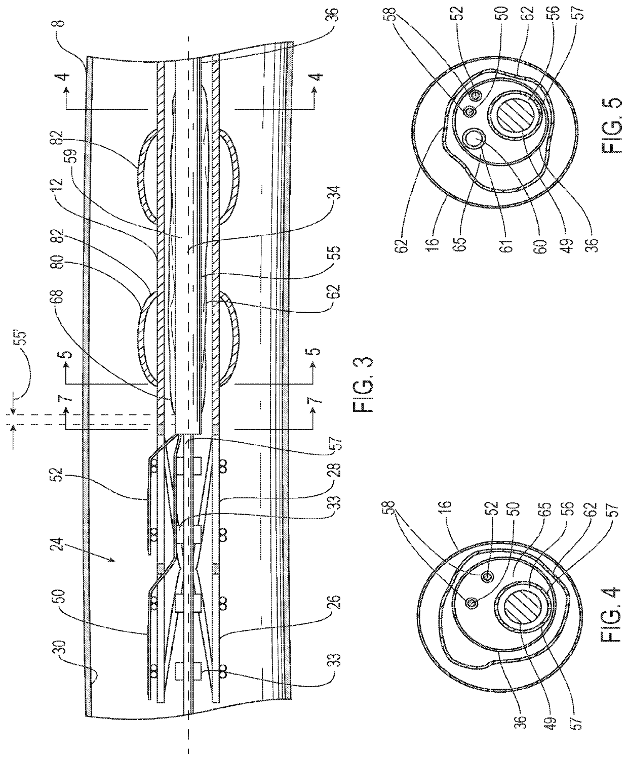
[0050]Referring to FIG. 3, the endoluminal prosthesis 12 may also have a self-expanding anchor member 24 that has a proximal portion 26 and a distal portion 28 with a distal end of the distal portion being secured to a proximal end 20 of the tubular main graft portion and a distal end of the proximal portion being secured to a proximal end of the distal portion. The self-expanding anchor member embodiment 24 shown in FIG. 2 has a generally cylindrical configuration with a free unsecured end at a proximal end thereof and a distal end that is secured to a proximal end of the main graft body. The proximal portion 26 of the self-expanding anchor member 24 may include a cylindrical stent including an elongate superelastic element disposed in a zig-zag configuration and the distal portion of the self-expanding anchor member comprises a cylindrical stent including an elongate superelastic element disposed in a zig-zag configuration. An optional connector ring (not shown) may be embedded in...

embodiment 14

[0059]In some instances, the friction generated by axial movement of the first and second release members 50, 52 may be minimized by using a multi-lumen configuration in the elongate shaft 36 of the delivery catheter 14. Such a delivery catheter embodiment 14 may include an elongate shaft 36 with one or more release member lumens 58 extending within a release member sleeve 67, a guidewire lumen 56 extending within a guidewire tube 57 for passage of a guidewire 49, an inflation lumen 60 for inflation of an inflatable balloon 62 extending within an inflation tube 61 and an optional fill lumen 64 for filling an optional inflatable portion of the endoluminal prosthesis 12 extending within a fill tube 69. The section of the elongate shaft 36 of the delivery catheter embodiment 14 shown in FIG. 5 illustrates the release member lumens 58 and guidewire lumen 56, surrounded by guidewire tube 57. The section in FIG. 4 also includes the inflation lumen 60 surrounded by the inflation tube 61.

[0...


PUM


Abstract

Delivery system embodiments for treatment of a vascular defect of a patient's vasculature that may include an endoluminal prosthesis loaded on a delivery catheter. In some cases, an inflatable balloon used to facilitate deployment of the endoluminal prosthesis may be disposed within an inner lumen of a tubular graft portion of the endoluminal prosthesis.

Description

CROSS-REFERENCE TO RELATED PATENT APPLICATIONS[0001]This patent application is a Continuation of U.S. application Ser. No. 15 / 576,241, filed Nov. 21, 2017, which is a national stage application under 35 U.S.C. § 371 of International Patent Application No. PCT / US2016 / 034427, filed May 26, 2016, which claims priority from U.S. Provisional Application No. 62 / 167,247, filed May 27, 2015, incorporated herein by reference in its entirety.BACKGROUND[0002]An aneurysm is a vascular defect indicated generally by an expansion and weakening of the wall of an artery of a patient. Aneurysms can develop at various sites within a patient's body. Thoracic aortic aneurysms (TAAs) or abdominal aortic aneurysms (AAAs) are manifested by an expansion and weakening of the aorta which is a serious and life threatening condition for which intervention is generally indicated. Existing methods of treating aneurysms include invasive surgical procedures with graft replacement of the affected vessel or body lume...

Claims


Application Information

Patent Timeline
Patent Type & Authority Applications(United States)
IPC IPC(8): A61F2/958A61F2/07A61F2/966
CPCA61F2/966A61F2210/0014A61F2/958A61F2230/0069A61F2002/067A61M2025/1061A61F2002/065A61M2025/1004A61F2220/0016A61F2/07A61F2250/0098A61F2250/0003A61M25/0032A61F2002/9583A61F2002/9665A61F2002/9511
Inventor GEUSEN, MARK
Owner TRIVASCULAR2
Why Eureka
Try Eureka