Small-diameter spark plug with resistive seal

a resistive seal and small diameter technology, applied in the field of spark plugs, can solve the problems of reducing the dielectric capacity of the spark plug, affecting the performance and safety of the plug, and producing performance and safety related malfunctions, so as to avoid pressure build-up during assembly, increase the dielectric capacity, and reduce the effect of rfi

Active Publication Date: 2008-11-20
TENNECO
View PDF17 Cites 13 Cited by
  • Summary
  • Abstract
  • Description
  • Claims
  • Application Information

AI Technical Summary

Benefits of technology

[0015]The invention overcomes the shortcomings and disadvantages of the prior art designs due to the intermediate tapered section of the central passage, which advantageously self-centers the connecting pin within the central passage in such a manner so as to avoid pressure build-up during assembly. Furthermore, the intermediate tapered section creates an increase in insulator wall thickness, thus providing increased dielectric capacity and greater column strength in the body of the insulator within compression and dielectric puncture zone regions.

Problems solved by technology

This EMI (or RFI) can interfere with entertainment radio, two-way radio, television, digital data transmissions or any type of electronic communication.
Ignition EMI is a nuisance and in extreme cases can produce performance and safety related malfunctions.
While internal resistor / suppressor spark plug designs are well known, practical considerations have frustrated the ability to integrate a resistor in small diameter spark plugs, for example those sized to fit a 12 mm or less (10 mm, 8 mm, etc.) diameter threaded bore.
In particular, the fairly large cross-sectional area required for the resistor inside the insulator weakens the structural integrity of the ceramic insulation by creating a thin wall section precisely in the region of an insulator which is often highly stressed during assembly and operation.
Heating of the upper terminal stud results in oxidation and discoloration of the terminal.
For example, the smooth piston-like fit of the connecting pin within the central passage has the potential to trap gasses during assembly, thereby creating gas bubble inclusions within the glass seal which degrade electrical performance during use.
This may also cause stress that could burst the side walls of the ceramic insulator under pressure.
Furthermore, in high thermal cycling events over prolonged use, it is possible that the connection between the threaded lower portion of the connecting pin and the enveloping glass seal may break loose due to differing rates of thermal expansion and the thermal stresses that result during cycling.
However, a design of the type depicted in FIG. 2 presents certain difficulties of its own.
Loss of control of the position of the pin during processing can result in unacceptable variations in the resistance of the finished spark plug.
These issues are mentioned above and include a thinning of the insulator wall in critical areas, such that the dielectric capacity of the insulator material may be breached.
Furthermore, these thinned sections of insulator wall become failure points when, during assembly, the shell is clamped about the exterior of the insulator, thereby placing a region of the insulator in compression.
Thin sections of the insulator wall are thus susceptible to catastrophic failure during compression loading.
Thus, as the spark plug is scaled down to accommodate smaller sized applications, the proportional decrease in wall thickness of the insulator can result in dielectric breach and / or compression load failure.
Accordingly, the current trend toward reduced diameter spark plugs introduces many practical difficulties.
The insulator wall thickness area of fired-in suppressor seal components experiences weakened structural integrity.
Furthermore, the current technique of heating the upper terminal stud together with the sealing glasses in a furnace results in oxidation and discoloration of the upper terminal stud which detracts aesthetically and contributes to connector installation problems.

Method used


Image

  • Small-diameter spark plug with resistive seal
  • Small-diameter spark plug with resistive seal
  • Small-diameter spark plug with resistive seal

Examples


Embodiment Construction

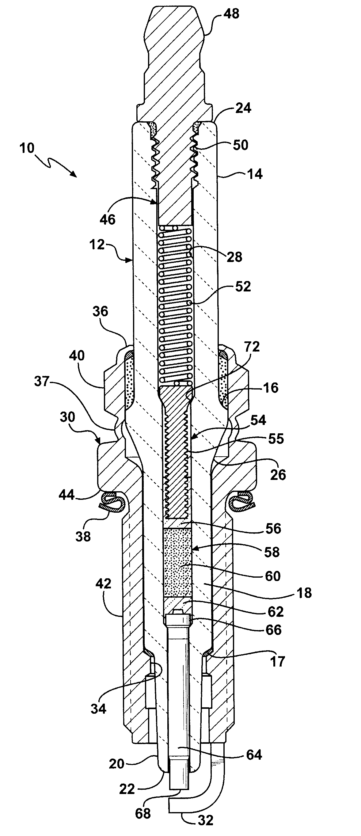
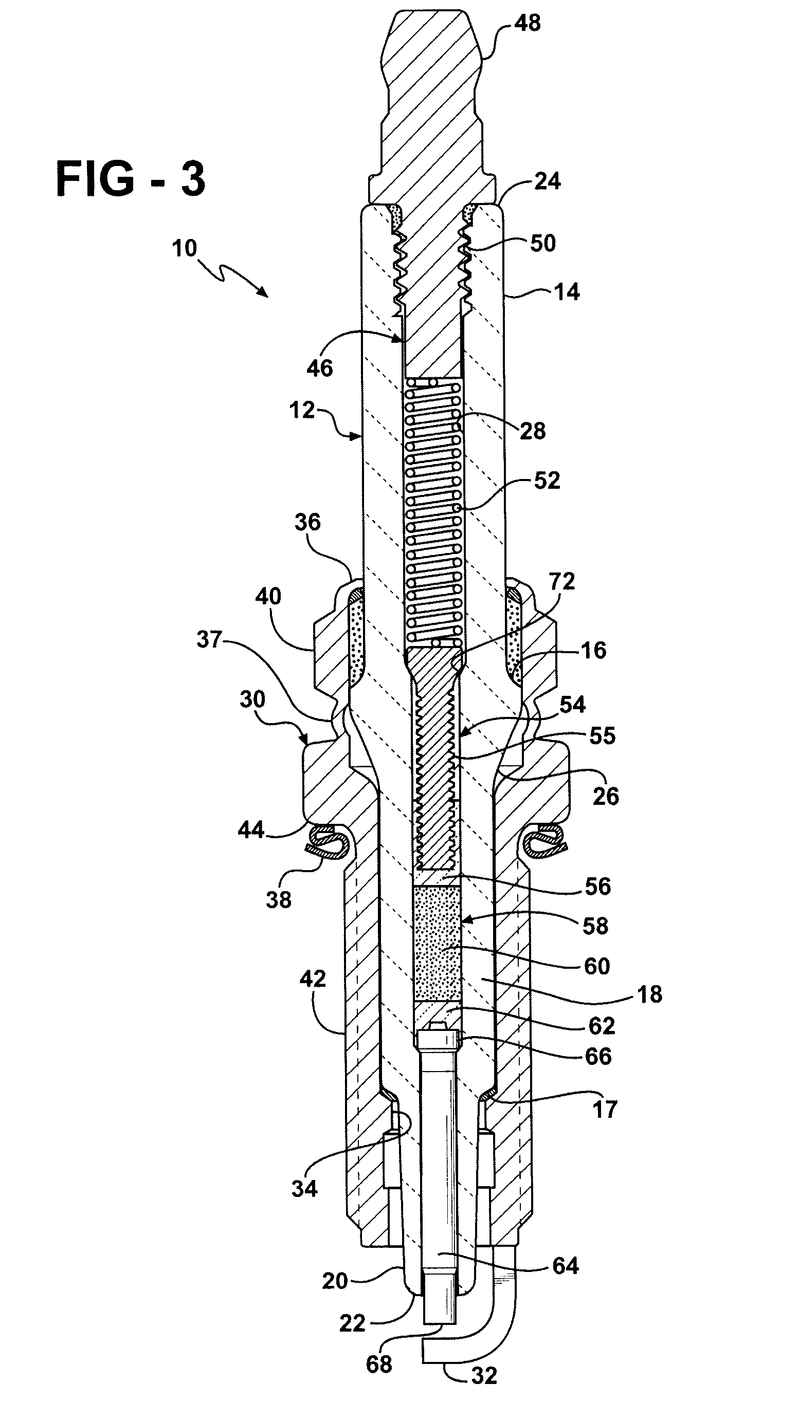
[0025]Referring to the Figures, wherein like numerals indicate like or corresponding parts throughout the several views, a spark plug according to the subject invention is generally shown at 10 in FIG. 3. The spark plug 10 includes a tubular ceramic insulator, generally indicated at 12, which may be made from an aluminum oxide ceramic or other suitable material having the desired dielectric strength, mechanical strength and resistance to heat shock. The insulator 12 may be molded dry under extreme pressure and then kiln-fired to vitrification at high temperature. However, those skilled in this art will appreciate that methods other than dry pressing and sintering may be used to form the insulator 12. The insulator 12 has an outer surface which may or may not be glazed about its exposed portions. The insulator 12 may include a partially exposed upper mast portion 14 to which a rubber spark boot (not shown) surrounds and grips to establish a connection with the ignition system. The ex...


PUM


Abstract

A spark plug (10) includes an intermediate connecting pin (54) disposed in the central passage (28) of an the insulator body (12). The connecting pin (54) seats in an intermediate taper section (72) within the central passage (28), which is generally frustoconical and establishes a transition between a first larger diameter of the central passage (28) and a second smaller diameter. The intermediate tapered section (72) is located longitudinally above a filleted transition (26) feature of the insulator body (12) exterior. A pin head (53) of the connecting pin (54) has a complementary tapered under-cut and seats against the intermediate tapered section (72) to provide self-centering of the connecting pin (54) without trapping gas during the assembly process. The intermediate taper section (72) also provides an increase in insulator wall thickness which improves dielectric capacity and structural integrity of the insulator (12).

Description

CROSS REFERENCE TO RELATED APPLICATIONS[0001]The present application claims priority to U.S. provisional application having Ser. No. 60 / 938,516 and filed on May 17, 2007.BACKGROUND OF THE INVENTION[0002]1. Field of the Invention[0003]The subject invention relates to a spark plug for a spark-ignited internal combustion engine, and more particularly toward a spark plug having a fired-in suppressor seal contained in the insulator between a lower center electrode and an intermediate connecting pin.[0004]2. Related Art[0005]A spark plug is a device that extends into the combustion chamber of an internal combustion engine and produces a spark to ignite a mixture of air and fuel. In operation, charges of up to about 40,000 volts are applied through the spark plug center electrode, thereby causing a spark to jump the gap between the center electrode and an opposing ground electrode.[0006]Electromagnetic interference (EMI), also known as radio frequency interference (RFI), is generated at th...

Claims


Application Information

Patent Timeline
Patent Type & Authority Applications(United States)
IPC IPC(8): H01T13/20H01T21/02
CPCH01T13/34H01T21/02H01T13/41H01T13/20
Inventor HOFFMAN, JOHN W.
Owner TENNECO
Why Eureka
Try Eureka