Colliding obstacle detection apparatus for vehicle
- Summary
- Abstract
- Description
- Claims
- Application Information
AI Technical Summary
Benefits of technology
Problems solved by technology
Method used
Image

Examples
first embodiment
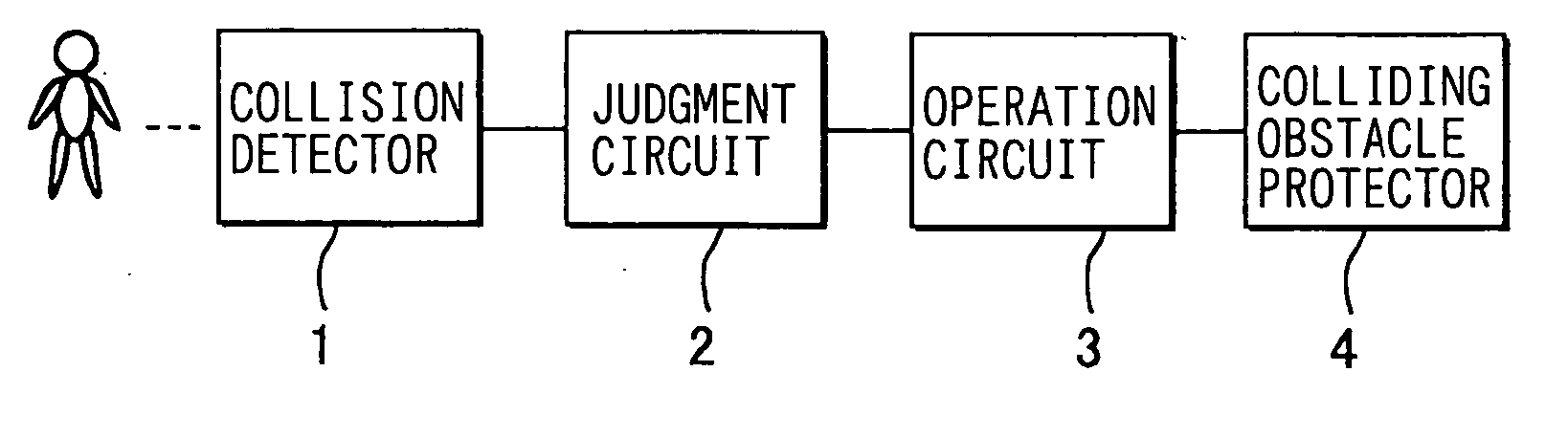
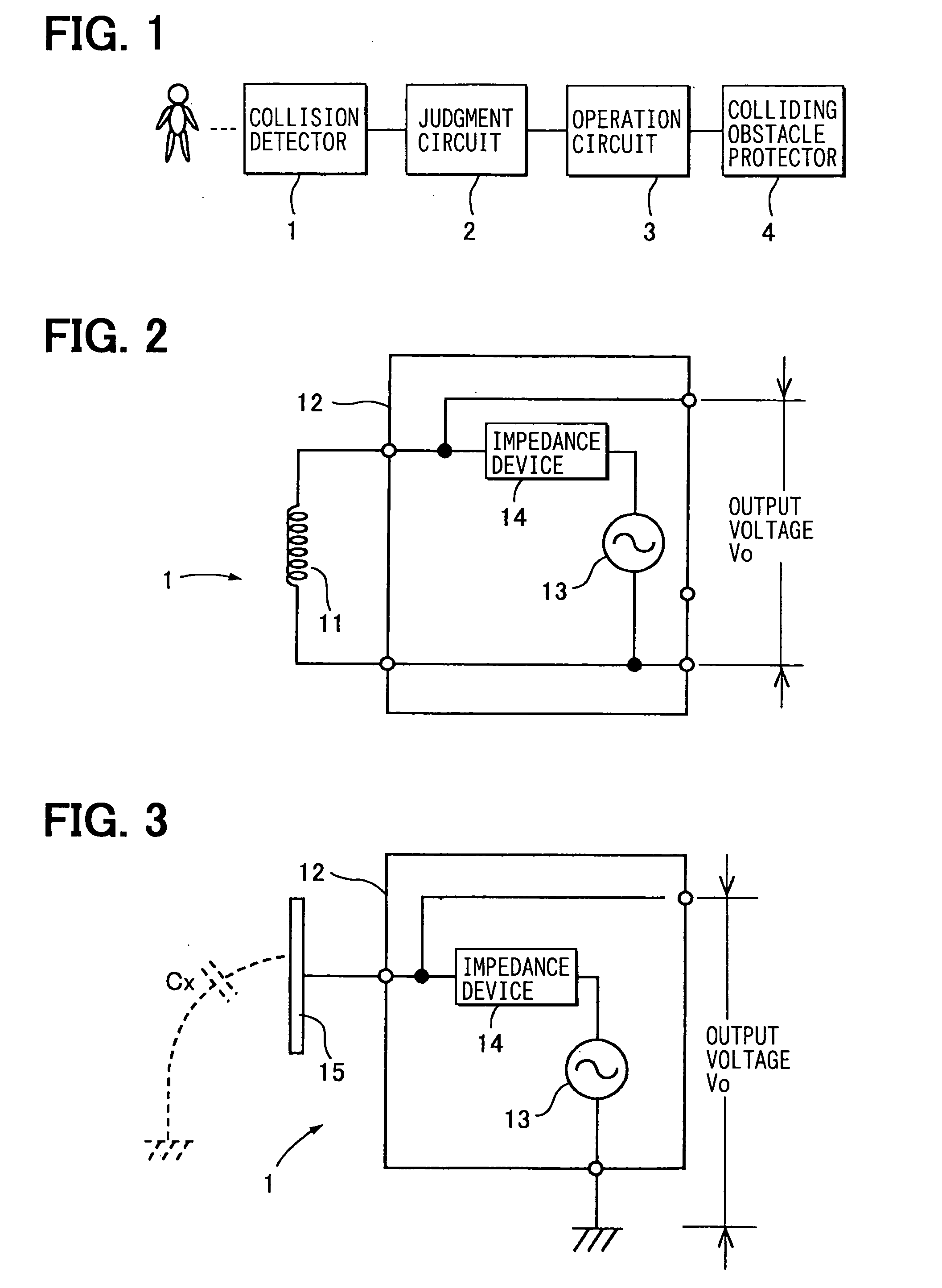
[0031]FIG. 1 depicts a block diagram of a colliding obstacle detection apparatus of this embodiment. Collision detector 1 detects an obstacle colliding with the pedestrian bumper described later. A judgment circuit 2 determines whether a collision has occurred and classifies the colliding obstacle based on the output voltage sent by the collision detector 1. In a case that the judgment circuit 2 determines a collision has occurred and classifies the colliding obstacle is a pedestrian, the judgment circuit 2 outputs a signal. An operation circuit 3 receives the signal and operates a colliding obstacle protector 4. The operation circuit 3 inhibits the colliding obstacle protector 4 from operating without receiving the signal. The judgment circuit 2 and the operation circuit 3 compose the control circuit of the present invention.
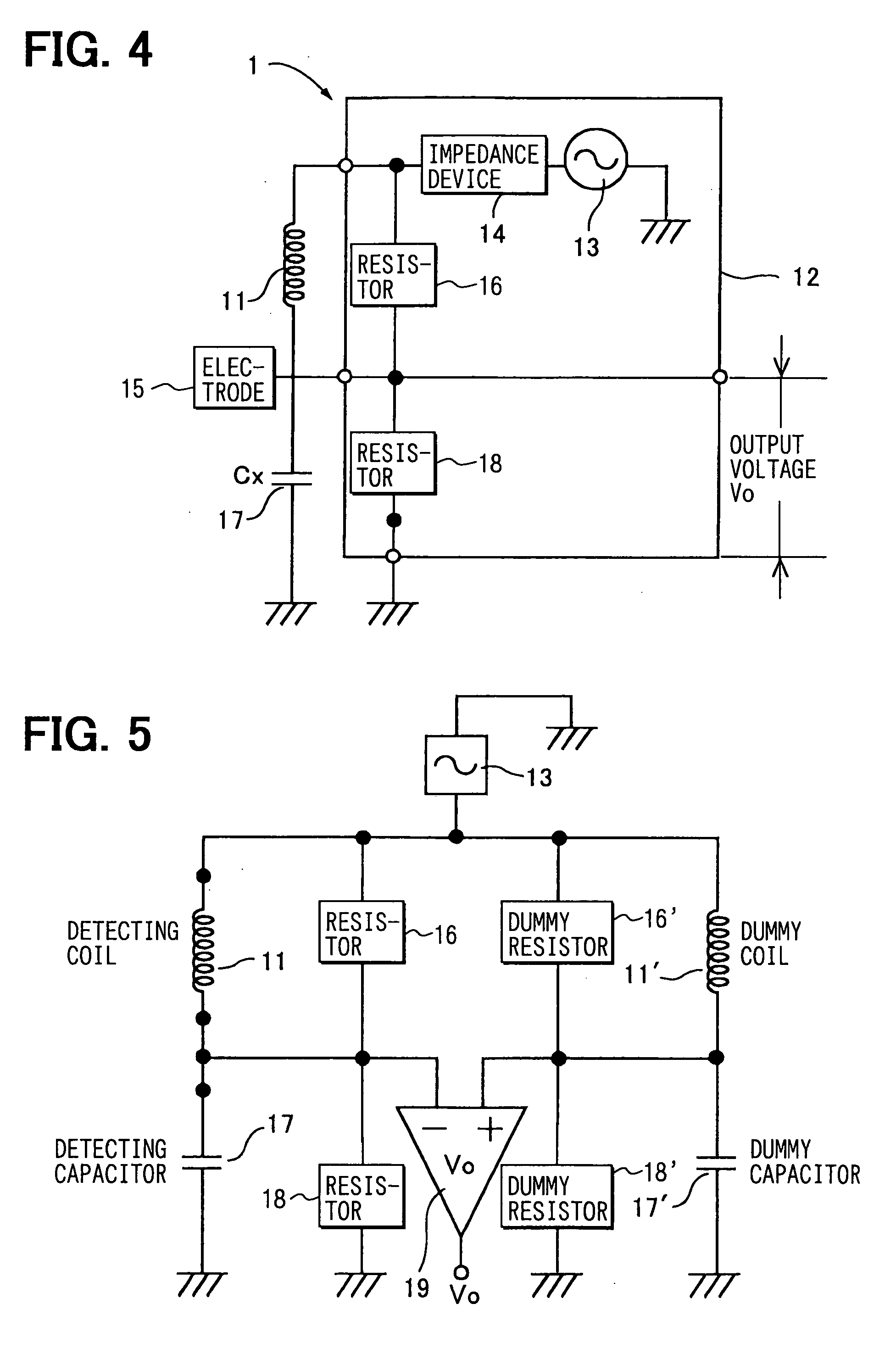
[0032]FIG. 2 depicts an example of the collision detector 1. A coil 11 is located on a bumper plate of a pedestrian bumper. An electricity supply circuit 12 s...
second embodiment
[0065] Another embodiment of the present colliding obstacle detection apparatus will be described hereinafter referring to FIGS. 11 and 12. In these Figures, the extendable pedestrian bumper 20 is extended.
[0066] On front face of the vehicle body 100 is provided front bumper 50 comprising a bumper cover 51 and a bumper absorber 52 covered with the bumper 51. The bumper absorber 52 is located in front of a bumper reinforcement 53. The bumper reinforcement 53 is fixed at the front end portion of the side members 54.
[0067] As shown in FIG. 12, below the front bumper 50 is located an extendable pedestrian bumper 20. The pedestrian bumper 20 comprises a pair of actuators 60 each of which is fixed on the side member 54, rods protruding forward from the actuators 60 and a plastic bumper plate 21 supported by the two rods and extending from side to side. Wiring 22 connects sensors 1, 200 and a control unit 70. Stays 23 support the rods slidably forward and backward and are fixed onto the ...
third embodiment
[0071] The third embodiment is described referring to FIG. 15. In the third embodiment, an oil cylinder supplied with hydraulic pressure from a hydraulic pump system 52 implements the actuator 60. The rods above are piston rods of the cylinders. The hydraulic cylinder 60 has a pressure sensor 61 detecting the pressure in the hydraulic chamber in the hydraulic cylinder 60. The hydraulic cylinders 60 protrude and retract the rods. When a pedestrian collides with the bumper plate21, the rods retract suddenly by the collision impact and the oil pressure in the oil cylinder 60 suddenly increases temporary. It is possible to detect the colliding load by detecting the oil pressure by the oil pressure sensor 61.
PUM
 Abstract
Description
Claims
Application Information
 - R&D Engineer
- R&D Manager
- IP Professional
- Industry Leading Data Capabilities
- Powerful AI technology
- Patent DNA Extraction
Browse by: Latest US Patents, China's latest patents, Technical Efficacy Thesaurus, Application Domain, Technology Topic.
© 2024 PatSnap. All rights reserved.Legal|Privacy policy|Modern Slavery Act Transparency Statement|Sitemap