Wind power machine

a wind power machine and wind power technology, applied in the direction of motors, engine fuctions, motors, etc., can solve the problems of high installation difficulty, high weight of the generator, and high cost of the machine, and achieve the effect of easy maintenance and replacement, reduced cost, and easy brakes

Inactive Publication Date: 2005-07-21
NIKOLAUS THOMAS
View PDF5 Cites 31 Cited by
  • Summary
  • Abstract
  • Description
  • Claims
  • Application Information

AI Technical Summary

Benefits of technology

[0016] One advantage of the present invention in this case is that the output load, which may be any desired output load, but is preferably a generator, can be arranged close to the ground or in the base area of the pylon, or in the ground area away from the pylon.
[0017] The output load can then easily be maintained and replaced, if necessary, in the event of wear.
[0018] A further significant advantage is that two or more wind power machines, possibly also of different types or in a wind park, can be connected to the single converter and to the single output load, in particular a generator, so that only one generator need be provided in order to convert the pressure energy that is produced from the hydraulic pumps to electrical energy.
[0019] This allows wind parks to be designed, operated and maintained at a considerably lower cost.
[0020] Furthermore, it has been found to be advantageous to insert a restriction element into the line for control purposes, in particular in order to limit the rotation speed of the rotor element for critical rotation speeds, which restriction element can be controlled such that a critical rotor element speed can be regulated via the flow rate through the restriction. This allows the rotor element to be braked very easily, without wear and at low cost. There is therefore no need for costly, heavy, conventional brakes.
[0021] The insertion of controllable valves into the line as well as the return line, or possibly in the hydraulic pump itself, also allows the rotor element to be fixed such that it cannot rotate, and the wind power machine can be switched on in a simple and cost-effective manner, without any wear. This is likewise intended to be within the scope of the present invention.

Problems solved by technology

This has the disadvantage that the weight of the generator, in particular of a very high-power generator, is at a very high level, and very severe oscillations often occur when the wind loads are high with very large wind power machines with tall pylons, so that the wind power machine must be switched off.
A further disadvantage is that the heavy weight of the generator, in particular, makes installation more difficult since costly cranes are required in order to fit the pylon attachment to the pylon.
A further disadvantage is that the maintenance work on the generator and, if appropriate, on the intermediate transmission element is carried out in the pylon attachment, and the maintenance personnel have to enter the pylon attachment, which is time-consuming.
A further disadvantage with conventional wind power machines or wind parks is that, when the wind speeds are very high, they must be switched off owing to the very high rotation speeds of the rotor element, in order to prevent the wind power machines from oscillating in a correspondingly dangerous manner.
Furthermore, as is evident from the Weibull distribution, only quite specific wind spectra or ranges can be used and converted to a power output optimally, and this is disadvantageous.
A further disadvantage is that only a quite specific proportion of the energy is utilized, by means of conventional technology.
Furthermore, wind power machines such as these must be positively controlled in particular with respect to rotation of the pylon attachment, which likewise involves costs and control complexity.

Method used


Image

  • Wind power machine
  • Wind power machine
  • Wind power machine

Examples


Embodiment Construction

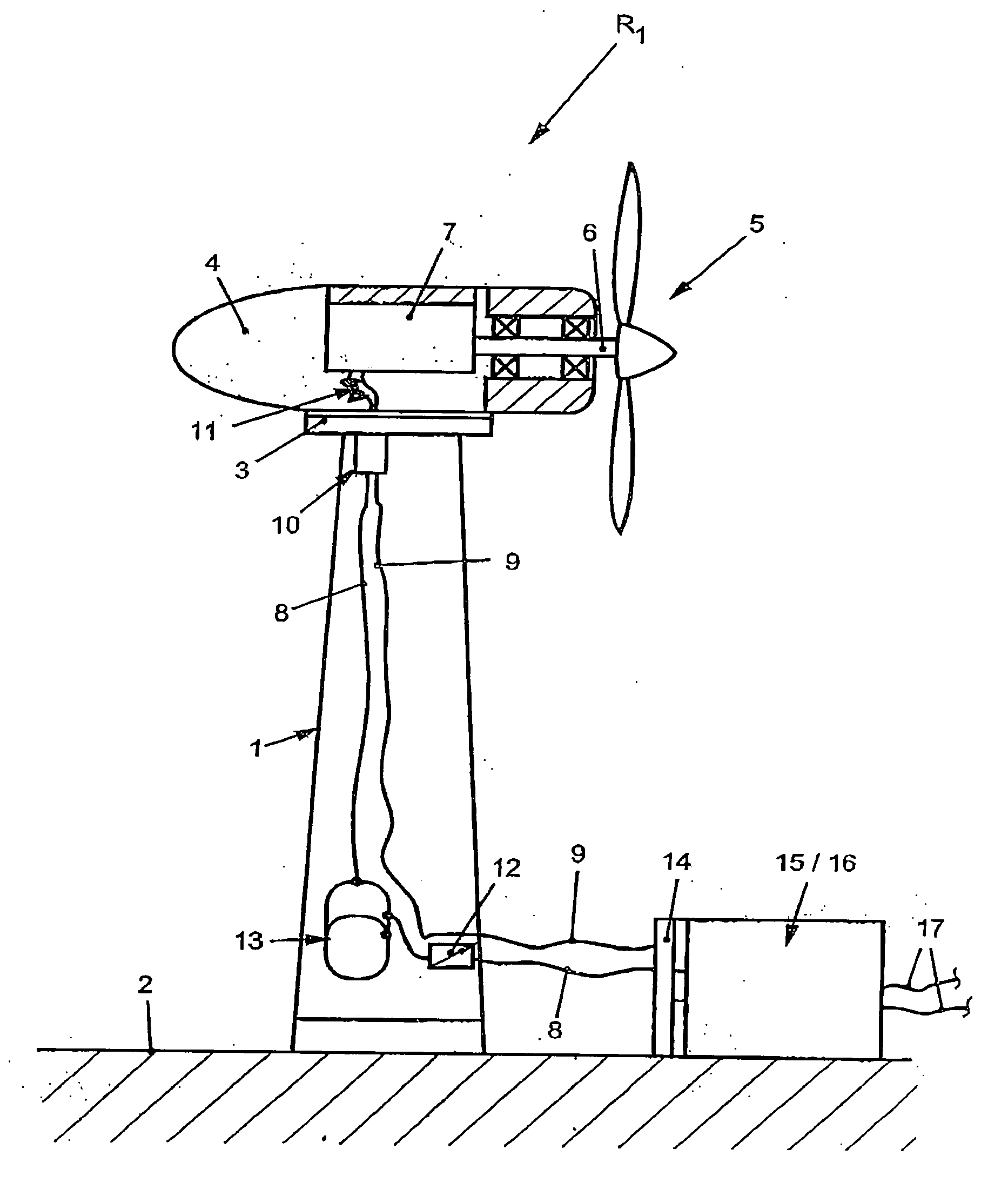
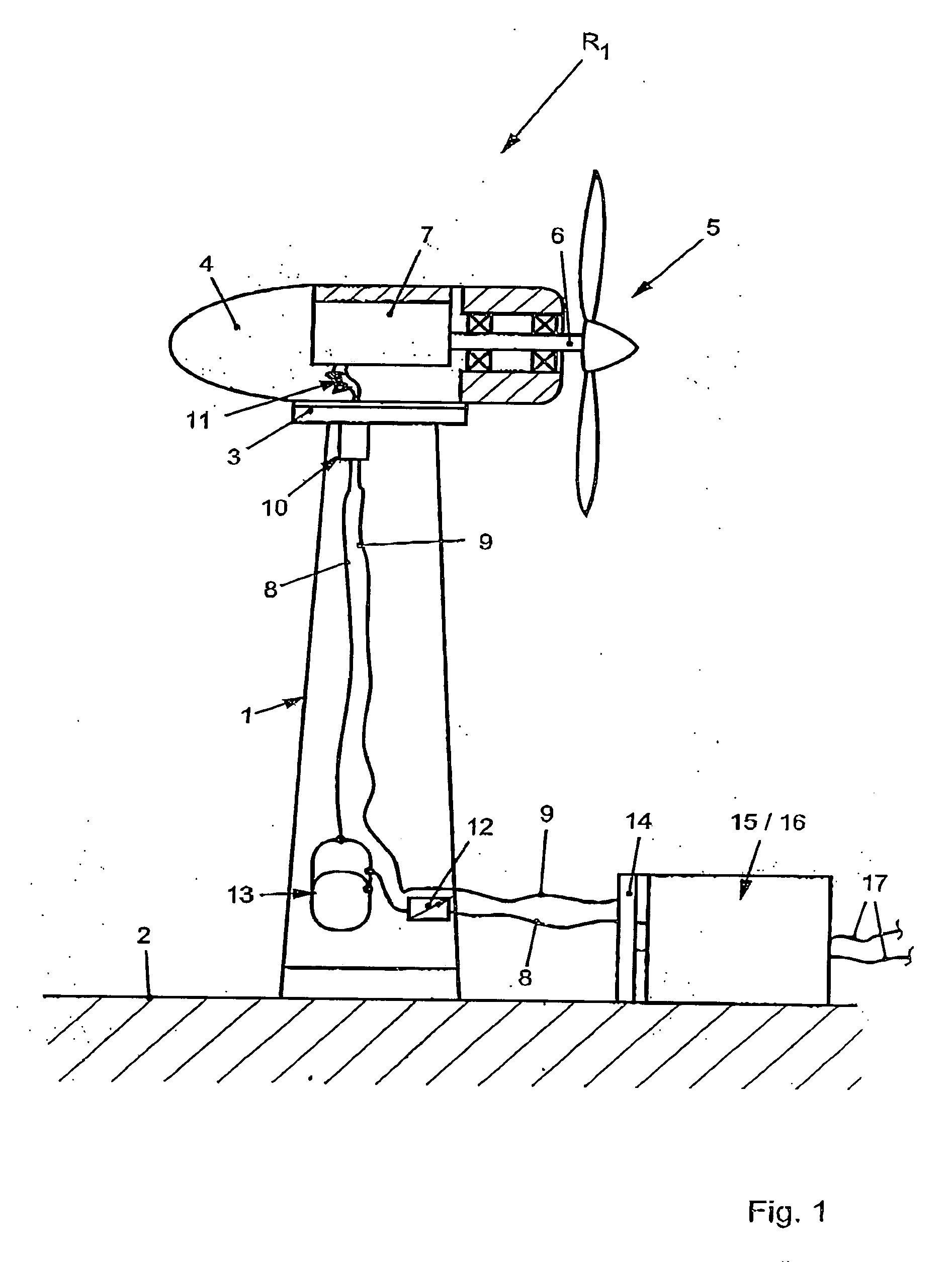
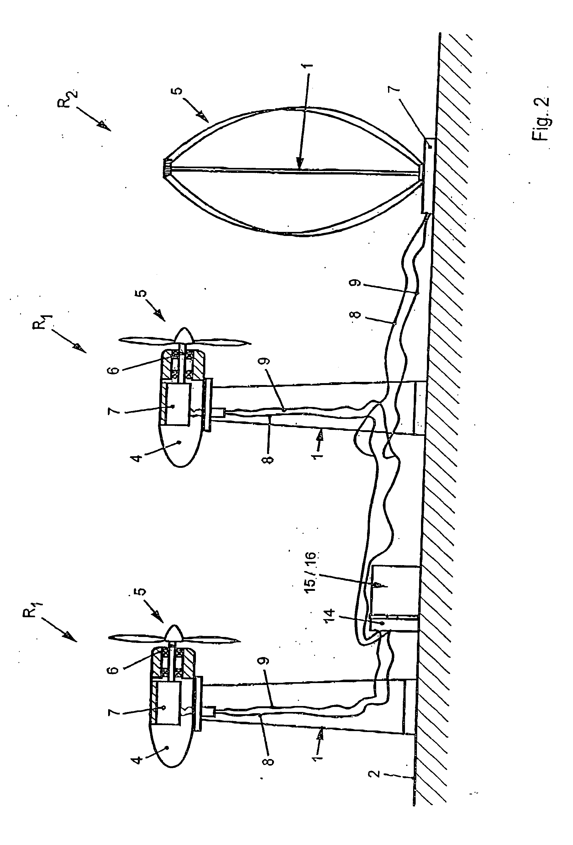
[0033] As is shown in FIG. 1, a wind power machine R1 according to the invention has a pylon 1 which is installed on a base 2. The pylon 1 is seated on a pylon attachment 4 via a bearing element 3 such that it can rotate, and the pylon attachment 4 is fitted with at least one rotor element 5.

[0034] The rotor element 5 is driven by the wind such that it rotates about a rotor shaft 6.

[0035] According to the invention, the rotor shaft 6, and hence the rotor element 5, are connected to a hydraulic pump 7. The rotational movement of the rotor element 5 and of the rotor shaft 6 allows the hydraulic pump 7 to be driven and to produce a hydraulic pressure, which is passed on via a first line 8. A return line 9 is furthermore likewise connected to the hydraulic pump 7.

[0036] The line 8 and the return line 9 between the hydraulic pump 7 preferably open into a coupling 10, which compensates for and equalizes any rotational movement of the pylon attachment 4 with respect to the rigid pylon 1...


PUM


Abstract

A wind power machine for production of energy, comprises at least one rotor element (5) which can be driven by the wind and having an output load (15), in particular a generator (16), which is connected directly or indirectly to it, the rotor element (5) is intended to drive one or more hydraulic pumps (7) directly or indirectly.

Description

BACKGROUND OF THE INVENTION [0001] The present invention relates to a wind power machine for production of energy, having at least one rotor element which can be driven by the wind, and an output load, in particular a generator, which is connected directly or indirectly to it. [0002] Wind power machines such as these are commercially available in many different forms and embodiments and are used for the production of energy, in particular for electricity generation. Conventional wind power machines are generally formed from a pylon, to which a pylon attachment is fitted such that it can rotate. A generator, possibly a transmission and a rotor element connected to it are mounted in this pylon attachment. [0003] The rotor element is driven by the wind and transmits a rotary movement, possibly via an intermediate transmission, directly to a generator. [0004] This has the disadvantage that the weight of the generator, in particular of a very high-power generator, is at a very high level...

Claims


Application Information

Patent Timeline
Patent Type & Authority Applications(United States)
IPC IPC(8): F03D1/02F03D9/00F03D9/02F03D11/02
CPCF03D9/001Y02E10/722F05B2260/406F03D11/02F03D15/00F03D9/28Y02E10/72Y02E60/16Y02P80/10Y02E70/30F03D1/02F03D3/02F03D9/17F03D9/25
Inventor NIKOLAUS, THOMAS
Owner NIKOLAUS THOMAS
Why Eureka
Try Eureka