
Lane-change assistant for motor vehicles

a technology for motor vehicles and assistants, applied in brake systems, instruments, transportation and packaging, etc., can solve problems such as not conforming to drivers' actual requirements, and achieve the effect of increasing driving speed and high dynamics

Inactive Publication Date: 2005-07-21
ROBERT BOSCH GMBH
View PDF5 Cites 64 Cited by
  • Summary
  • Abstract
  • Description
  • Claims
  • Application Information

AI Technical Summary

Benefits of technology

[0004] An object of the present invention is to create a lane changing assistant which permits the sequence of the lane changing operation to be better adapted to the driver's intent.
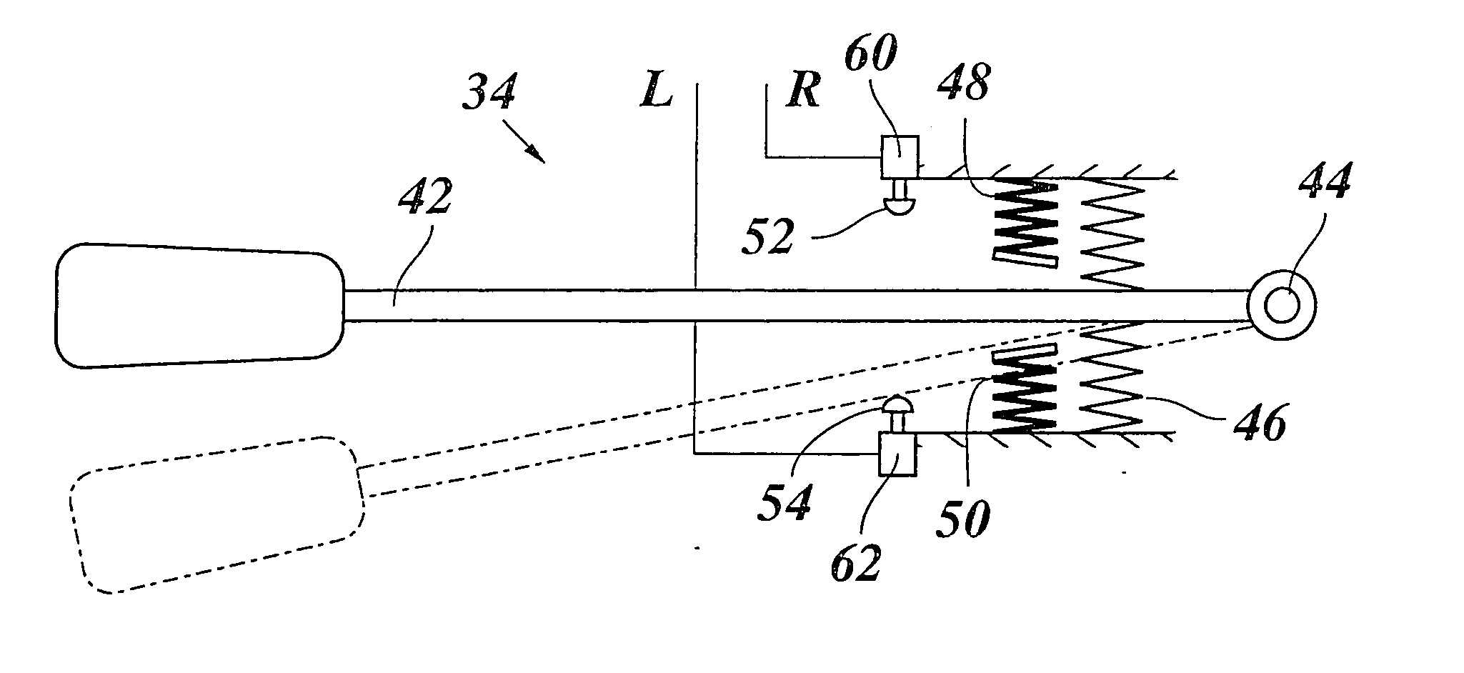
[0005] This object is achieved according to the present invention by the fact that a sensor is assigned to the operating element for each adjustment direction and the sensor supplies a multi-valued output signal corresponding to the operation of the operating element, and this output signal determines the dynamics of the lane changing operation.
[0006] The term “dynamics of the lane changing operation” refers to the speed with which the lane change is completed. With low dynamics, the lane changing operation extends over a longer period of time and the steering angle remains relatively small, so that the transverse acceleration of the vehicle which occurs in changing lanes remains low accordingly. This permits lane changing with a great convenience in traffic situations in which a sufficient amount of time is available for changing lanes. However, a more dynamic lane changing operation is required in other traffic situations, e.g., when a vehicle to be passed in front brakes suddenly, i.e., the vehicle changes to the next lane more rapidly and therefore higher transverse accelerations occur. The present invention offers the driver the option of controlling the dynamics of the lane changing operation as desired.
[0009] The dynamics of the lane changing operation may be influenced in various ways, e.g., by the speed at which the setpoint changes, by limiting the steering angle, which is determined by the output signal of the regulator, or by direct modification of this output signal. The control algorithm for the lane keeping support is frequently designed so that a measured setpoint / actual deviation within a certain driving distance, called the forecast distance, is reduced to zero. The forecast distance is at least dependent upon speed and therefore is preferably given in the form of a time interval, the forecast time which is equal to the quotient of the forecast distance and the absolute speed of the vehicle. With a short forecast time, the steering deflection must be more intense to regulate the transverse position of the vehicle back to the setpoint value within this forecast time. If the setpoint value is now to be changed by the lane keeping assistant, high dynamics of the lane changing operation may consequently be achieved through a choice of a short forecast time.
[0014] In a modified embodiment, the lane changing procedure is controlled automatically from the beginning and the dynamics is determined in operation of the operating element, e.g., on the basis of the maximum value of the sensor signal, and then remains in effect for the entire lane changing procedure. Instead of exerting a measured force on the sensor, in this case it may be more expedient to measure the time during which the driver is pressing the operating element against the stop. In this way the driver is able to trigger a slow lane changing procedure by touching the operating element. If the driver desires a more rapid lane change, he will hold the operating element in the stop position for a longer period of time. According to another modification, it is conceivable to provide multiple graduated pressure points instead of the stop, in which case overcoming each pressure point will correspond to a lane change with higher dynamics.
[0015] The information regarding the driver's intent to change lanes obtained with the help of the operating element and the sensors may also be transmitted to other system components of the vehicle, preferably in digital form via a databus, e.g., a CAN bus, and may then be used, for example, as part of a radar-supported adaptive cruise control to adjust the tracking range of the radar according to the lane changing and / or to intervene in the longitudinal guidance system of the vehicle which belongs to the ADAS system and to increase driving speed—e.g., in a passing operation.

Problems solved by technology

After the lane changing command has been entered, the lane changing operation runs in automatic operation according to a fixedly predetermined program, but this often does not conform to the driver's actual intent.

Method used


Image

  • Lane-change assistant for motor vehicles
  • Lane-change assistant for motor vehicles

Examples


Embodiment Construction

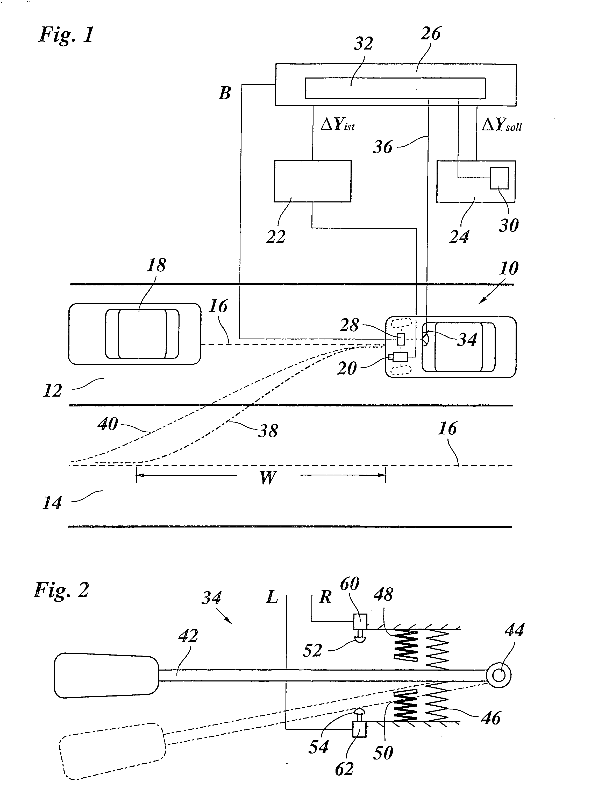
[0018]FIG. 1 shows schematically in a top view a motor vehicle 10, which is traveling in right lane 12 of a road which also has a passing lane 14. Center 16 of the lane is indicated by a dotted line. Vehicle 10 is now ready to pass a vehicle 18 in front.

[0019] Vehicle 10 is equipped with an ADAS system which as a component has a lane keeping system as a subsystem, having the following components illustrated in the form of a block diagram: a sensor device formed by a video camera 20 and an image processing unit 22, a selection device 24 for preselection of a setpoint ΔYsetpoint for the transverse position of vehicle 10, a regulating device 26 and a steering actuator element 28 which is triggered by a command signal B of regulating device 26 and intervenes in the vehicle steering to regulate the transverse position of vehicle 10 at the setpoint.

[0020] The actual position of the vehicle in the direction across its longitudinal axis is detected in the example shown here by the sensor ...


PUM


Abstract

Lane changing assistant for motor vehicles, controlling an automatic changing of the vehicle to a neighboring lane in response to a command by the driver as part of a lane keeping system of the motor vehicle and having an operating element that is movable in opposite directions out of a neutral position, wherein a sensor is assigned to the operating element for each adjustment direction and the sensor supplies a multi-valued output signal which corresponds to the operation of the operating element and determines the dynamics of the lane changing procedure.

Description

FIELD OF THE INVENTION [0001] The present invention a lane changing assistant which controls an automatic changing of the vehicle to a neighboring lane in response to a command by the driver as part of a lane keeping system; and an operating element which is movable from a neutral position into opposite directions. BACKGROUND INFORMATION [0002] Systems which support the driver in driving the vehicle or facilitate special driving maneuvers (advanced driver assistance systems; ADAS) are being used to an increasing extent in motor vehicles. One function of such systems is lane keeping support (LKS) in which the actual position of the vehicle in relation to the lane in which it is driving is determined and compared with a setpoint which typically corresponds to the center of the lane. The output signal then includes an actuator signal for an actuator which intervenes in the steering system of the vehicle, whether to support the driver by an additional steering torque or to perform a com...

Claims


Application Information

Patent Timeline
IPC IPC(8): B62D15/02B62D6/00B62D101/00B62D113/00
CPCB60T2201/08B62D15/0255B60T2201/087B62D1/00B62D1/02
Inventor BRAEUCHLE, GOETZBOECKER, JUERGEN
Owner ROBERT BOSCH GMBH
Learn More