Tool-less blade clamping apparatus for a reciprocating tool

a reciprocating tool and clamping technology, applied in the field of tools, can solve the problems of inconvenient attachment or removal of the tool attachment, and achieve the effect of convenient inserting

Inactive Publication Date: 2005-07-21
ROBERT BOSCH GMBH +1
View PDF55 Cites 20 Cited by
  • Summary
  • Abstract
  • Description
  • Claims
  • Application Information

AI Technical Summary

Benefits of technology

[0005] Several preferred embodiments of the present invention are disclosed herein for a tool-less blade clamping apparatus for a reciprocating tool of the type which has a reciprocating plunger which has a tool attachment receiving slot for receiving a tool attachment of the type that has a shank portion with at least one, and preferably two shoulders spaced from the end of the shank and an aperture in the shank for facilitating holding by the clamping apparatus. In all of the disclosed preferred embodiments shown and described herein, the clamping apparatus has an unclamped position and a clamped position where the shank portion of the tool attachment can be inserted into the slot as well as an opening in the apparatus itself. In the unclamped position, a tool attachment can be easily inserted and the shoulders will release the apparatus to move to the clamped position, where the tool attachment is securely retained. When returned to the unclamped position, the apparatus engages the shoulders and pushes the blade from the apparatus.

Problems solved by technology

Because such attachment mechanisms are often located in a confined space in the tool, it is often inconvenient to attach or remove the tool attachment, which can comprise a cutting blade, a saw blade, an abrasive, polishing or smoothing member or the like from the tool.
Moreover, since special tools were often required, it was necessary to have such tools available during use in the event the tool attachment breaks or otherwise needs to be changed because it is worn out or a different type of tool attachment is needed.
While mechanisms are known in the prior art that have this capability, the various known designs have varying degrees of effectiveness in securely holding the tool attachment in the tool, or in the ease and convenience of operation in mounting or removing tool attachments from the tool or in the degree of complexity and therefore cost of manufacture.

Method used


Image

  • Tool-less blade clamping apparatus for a reciprocating tool
  • Tool-less blade clamping apparatus for a reciprocating tool
  • Tool-less blade clamping apparatus for a reciprocating tool

Examples


first embodiment

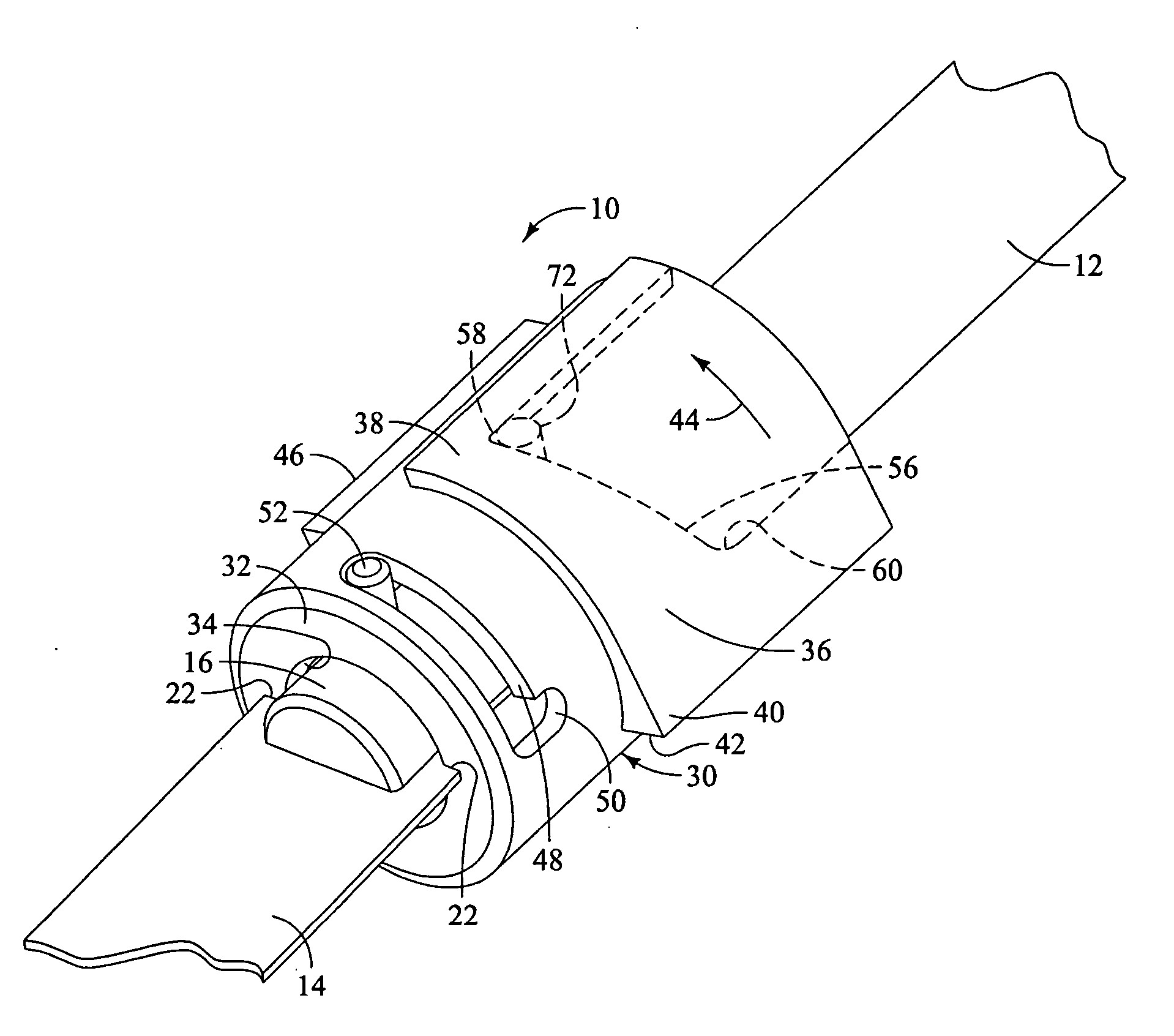
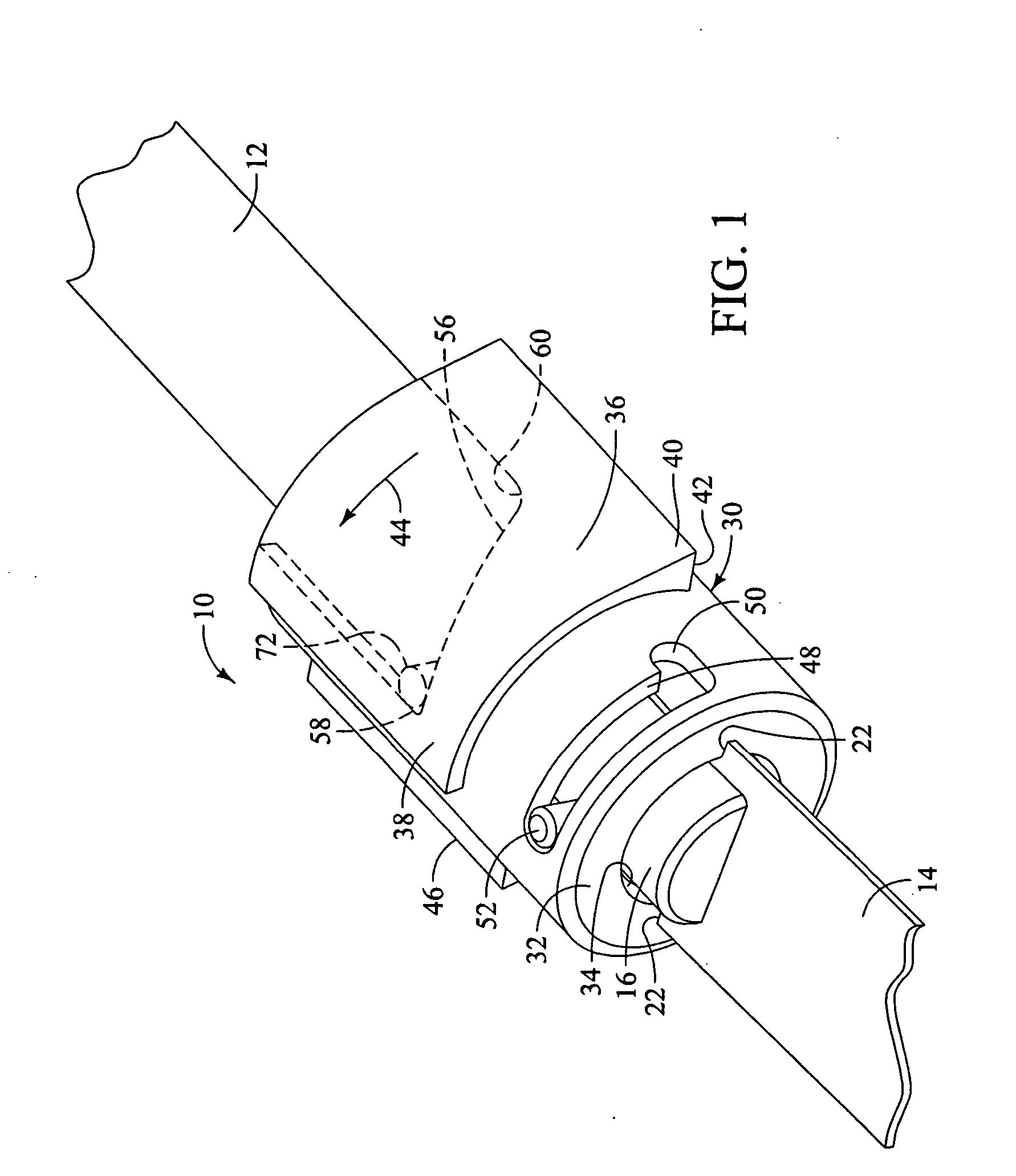
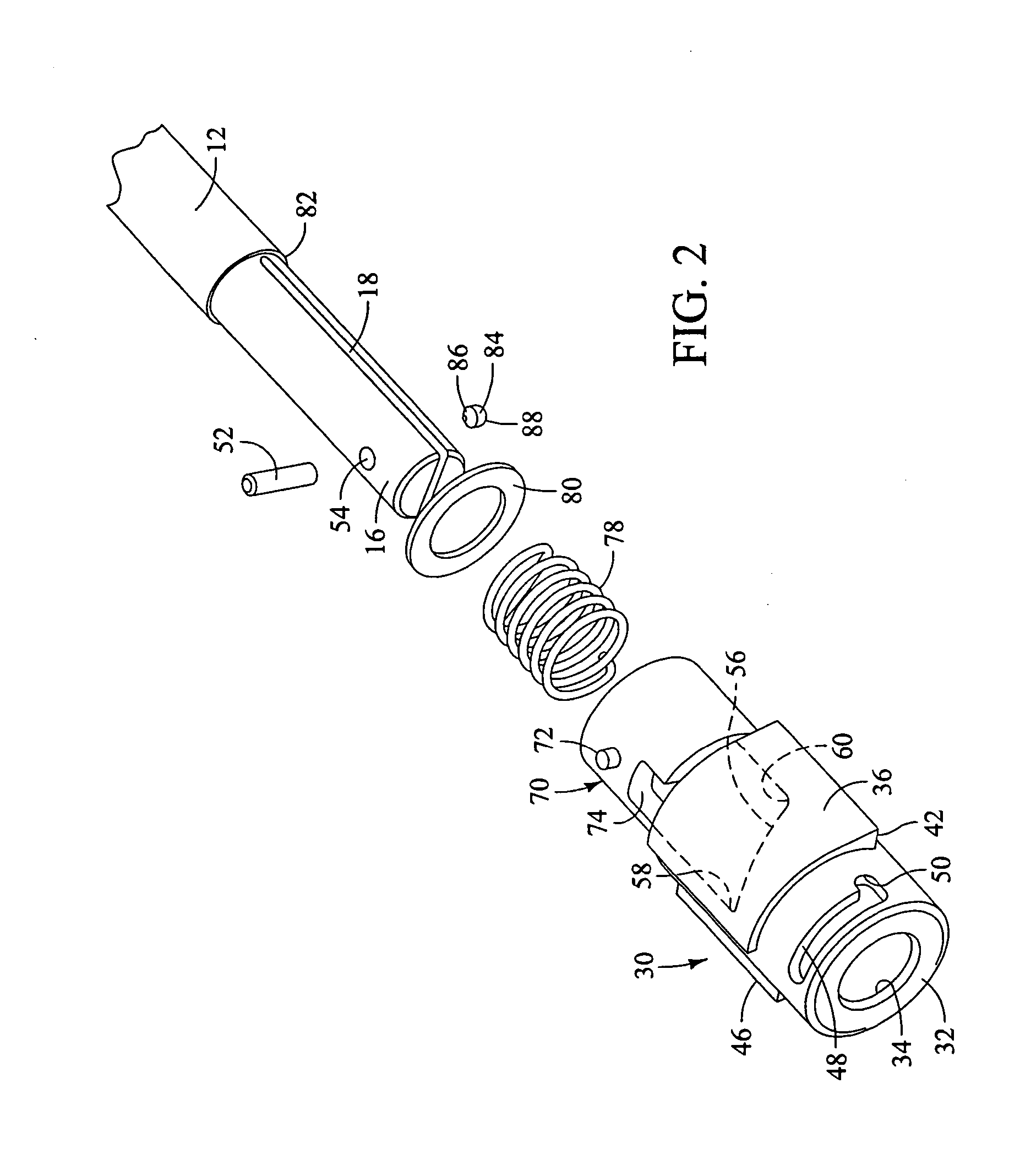
[0047] A generally cylindrical support ring 144 has a reduced diameter forward portion 146 that defines an annular shoulder 148 that is sized to engage the rear end surface of the control sleeve 102. The support ring 144 also has a rearward extension 152 (see FIGS. 13 and 14) that fits on the end portion 16 of the plunger rod 12. A compression spring 154 bears against the support ring 144 as well as against a generally cup-shaped spring retainer 156. The inside diameter of the rear end of the spring retainer is sized to closely fit the diameter of the end portion 16 and it contacts and is held by the annular shoulder 82 of the plunger rod 12. A detente 158 is provided and fits into an aperture 160 (see FIGS. 14 and 15) in the end portion 16 of the plunger rod. In this embodiment, the axial position of the aperture 160 and the aperture 54 are different as readily shown in FIG. 14. A smaller circular recess 162 is preferable ground into the face of the slot 18 adjacent to the conical ...

third embodiment

[0050] With regard to the third embodiment and referring to FIGS. 16-22, it is similar to the embodiment shown in FIGS. 11-15 in that the apparatus 200 has a cam surface that also engages a detente by rotation thereof. The assembled apparatus is indicated generally at 200 and is shown to be installed on a plunger rod 12 having a slightly reduced diameter end portion 16 which thereby forms the shoulder 82 as shown with regard to the prior described embodiments. The end portion 16 has a slot 18 for receiving the blade 14 which has the same configuration as has been described with regard to the first and second preferred embodiments. The apparatus 200 has a clamping collar, indicated generally at 202, that has an elongated slot 204 in which a pin 206 which is preferably force fit in an aperture 208 in the upper side of the end portion 16. Because the pin is secured in the plunger rod end portion 16 and the diameter of the pin is comparable to the width of the slot 204, the only movemen...

second embodiment

[0054] The detente 248 is moved toward and away from the blade 14 during operation by virtue of a cam surface 252 that is shown in FIG. 19 and which extends from approximately location 254 to location 256, with the location 256 having a larger radius from the center of the apparatus than the location 254. In this regard, it is similar to the cam surface of the

[0055] During operation of this embodiment, when a blade 14 is inserted into the slot 18 with the apparatus 200 in its unclamped position, the protrusion 210 of the clamping collar 202 is located in the axial slot 238 of the control sleeve 234. When the blade is pressed into the apparatus with sufficient force to travel a predetermined distance, the control sleeve 234 is moved axially in the reverse direction until the protrusion 210 is aligned with the annular groove 236 of the control sleeve 234, whereupon the bias of the torsion spring 230 will rotate the support ring 218 and the clamping collar 202 so that it moves in a clo...


PUM

PropertyMeasurementUnit
distanceaaaaaaaaaa
lengthaaaaaaaaaa
diameteraaaaaaaaaa

Abstract

Several preferred embodiments are disclosed for a tool-less blade clamping apparatus for a reciprocating tool of the type which has a reciprocating plunger which has a tool attachment receiving slot for receiving a tool attachment of the type that has a shank portion. The clamping apparatus has an unclamped position and a clamped position. In the unclamped position, a tool attachment can be easily inserted and when it is in its clamped position, the tool attachment is securely retained. The preferred embodiments have at least one spring biasing the apparatus toward the clamped position, a releasable retaining mechanism for holding the apparatus in its unclamped position after being placed in that position. When the blade shank portion is inserted into the slot a predetermined distance, the shoulders of the shank portion release the retaining mechanism to move it to its clamped position. When a blade is to be removed, the clamping apparatus needs only to be moved to its unclamped position by manually rotating the outer sleeve or collar, and the blade is normally ejected from the mechanism by contact with the blade shoulders as it reaches its unclamped position.

Description

BACKGROUND OF THE INVENTION [0001] The present invention generally relates to tools. More particularly, it relates to mechanisms for clamping tool attachments to such tools. [0002] While reciprocating tools such as jigsaws, saber saws and other reciprocating tools, including medical and surgical instruments, have been used for decades, the mechanisms for attaching a tool attachment to the reciprocating portion has evolved from various attachment mechanisms that required separate tools of one kind or another, typically screwdrivers, wrenches or levers, to attach the tool attachment to a reciprocating member by tightening screws or the like. Because such attachment mechanisms are often located in a confined space in the tool, it is often inconvenient to attach or remove the tool attachment, which can comprise a cutting blade, a saw blade, an abrasive, polishing or smoothing member or the like from the tool. Moreover, since special tools were often required, it was necessary to have su...

Claims


Application Information

Patent Timeline
Patent Type & Authority Applications(United States)
IPC IPC(8): B23D51/10
CPCB23D51/10B23B31/107Y10T279/17761Y10T279/17717Y10T279/17Y10T279/17743Y10T279/17803Y10T279/32Y10T279/17811Y10T83/9481
Inventor MARINI, MARC VINCENTROE, VANCE E.CARR, MATTHEWSINCLAIR, GARYWRIGHT, GAVIN
Owner ROBERT BOSCH GMBH
Why Eureka
Try Eureka