Alternating-current dynamoelectric machine

a dynamoelectric machine and alternating current technology, applied in the direction of engine starters, magnetic circuit rotating parts, magnetic circuit shape/form/construction, etc., can solve the problems of increasing costs proportionally, poor durability, and affecting the performance of the engine, so as to reduce the volume of permanent magnets, the effect of improving durability

Inactive Publication Date: 2005-07-21
MITSUBISHI ELECTRIC CORP
View PDF5 Cites 43 Cited by
  • Summary
  • Abstract
  • Description
  • Claims
  • Application Information

AI Technical Summary

Benefits of technology

[0010] An alternating-current dynamoelectric machine according to the present invention enables costs to be reduced and durability to be improved by reducing the volume of permanent magnets, and in the case of a generator-motor, for example, generates a large starting torque and has a reduced de-energized no-load induced voltage.

Problems solved by technology

In such constructions, one problem is that when the claw-shaped magnetic poles are viewed in a direction of rotation of the rotor, the permanent magnets protrude from a plane of projection formed by adjacent claw-shaped magnetic poles overlapping, and since protruding portions do not contribute to reductions in magnetic flux leakage, excessive volume is required in the permanent magnets to improve their properties, increasing costs proportionately.
Another problem is that increasing the volume of the permanent magnets also proportionately increases centrifugal force acting on the rotor, making durability poor.

Method used


Image

  • Alternating-current dynamoelectric machine
  • Alternating-current dynamoelectric machine
  • Alternating-current dynamoelectric machine

Examples


embodiment 1

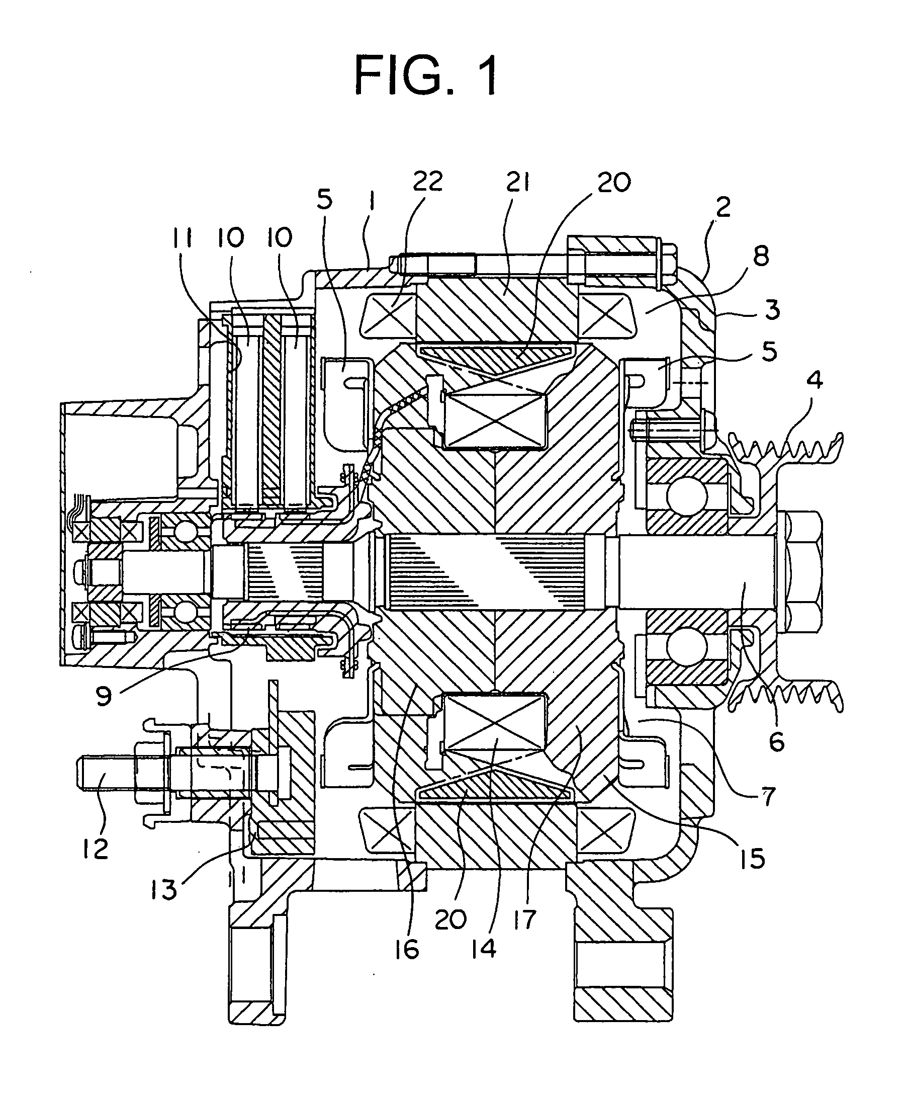
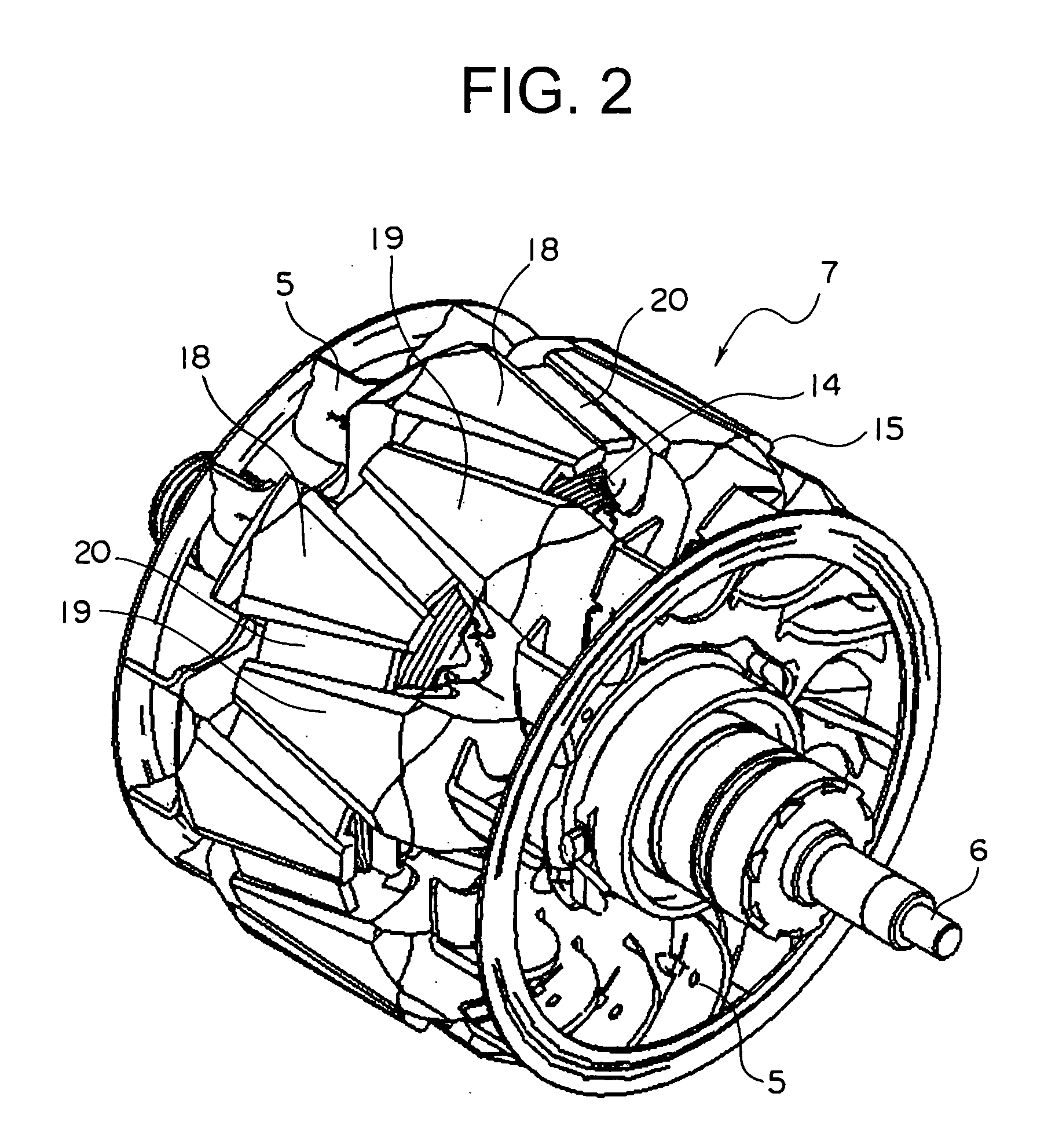
[0037]FIG. 1 is a cross section showing an automotive alternating-current generator-motor according to Embodiment 1 of the present invention, and FIG. 2 is a perspective of a rotor from FIG. 1.

[0038] This automotive alternating-current generator-motor (hereinafter “generator-motor”), which constitutes a dynamoelectric machine, includes: a case 3 constituted by a front bracket 1 and a rear bracket 2 made of aluminum; a shaft 6 disposed inside the case 3, a pulley 4 being secured to a first end portion of the shaft 6; a Lundell-type rotor 7 secured to the shaft 6; fans 5 secured to two end surfaces of the rotor 7; a stator 8 secured to an inner wall surface of the case 3; slip rings 9 secured to a second end portion of the shaft 6 for supplying electric current to the rotor 7; a pair of brushes 10 sliding on the slip rings 9; a brush holder 11 housing the brushes 10; a terminal block 12 disposed on the front bracket 1 for connecting to an inverter circuit (not shown); and a circuit b...

embodiment 2

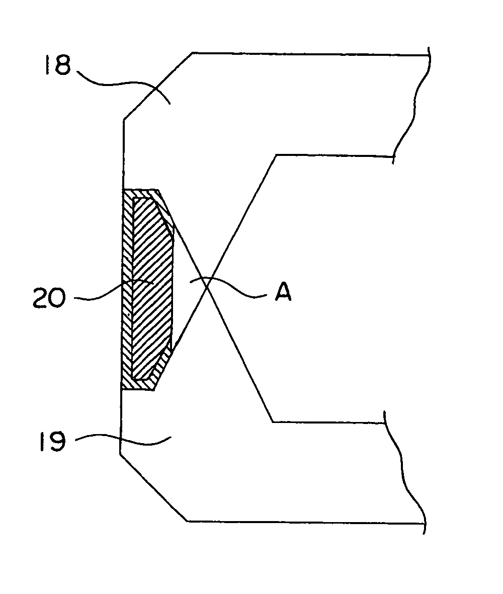
[0064] If the required starting torque is still not achieved by mounting the permanent magnets 20 within the plane of projection A of the adjacent claw-shaped magnetic poles 18 and 19, it may be necessary to increase the volume of the permanent magnets 20 further. Here, one simple way to increase the volume of the permanent magnets 20 is to increase the thickness of the permanent magnets 20 of the rotor 7 (dimensions in the direction of rotation of the rotor 7).

[0065] However, since there is only limited space between the adjacent claw-shaped magnetic poles 18 and 19, there is a limit to how much the thickness of the permanent magnets 20 can be increased.

[0066] Consequently, the necessity may arise to mount the permanent magnets 20 in portions protruding from within the plane of projection.

[0067] FIGS. 10 to 13 show examples in which a portion of the permanent magnets 20 protrudes out of the region of the plane of projection A, but the way in which each protrudes is different.

[0...

embodiment 3

[0072]FIG. 15 is a magnetic pole cross section when claw-shaped magnetic poles 18 and 19 are not parallel and when they are parallel, FIG. 16 is a perspective showing a case when the claw-shaped magnetic poles 18 and 19 are parallel, and FIG. 17 is a partial plan when permanent magnets 20 are mounted between the claw-shaped magnetic poles 18 and 19 shown in FIG. 15.

[0073]FIG. 18 shows magnetic leakage flux density when the claw-shaped magnetic poles 18 and 19 are not parallel and when they are parallel. When the claw-shaped magnetic poles 18 and 19 are not parallel, the total amount of magnetic flux (surface area in FIG. 18) is increased compared to when they are parallel, since the magnetic leakage flux φ where the distance between the claw-shaped magnetic poles 18 and 19 is narrow (on the radially-outer side of the rotor 7) increases in inverse proportion to the distance between the claw-shaped magnetic poles 18 and 19, but the amount of magnetic leakage flux can be reduced by ma...


PUM


Abstract

A projected shape of permanent magnets is contained within a plane of projection formed by adjacent claw-shaped magnetic poles overlapping when the claw-shaped magnetic poles are viewed in a direction of rotation of a rotor, and is generally similar in shape to a shape of the plane of projection.

Description

BACKGROUND OF THE INVENTION [0001] 1. Field of the Invention [0002] The present invention relates to an alternating-current dynamoelectric machine having a rotor in which permanent magnets are disposed between adjacent claw-shaped magnetic poles. [0003] 2. Description of the Related Art [0004] Conventionally, automotive alternators are known in which permanent magnets are disposed between adjacent claw-shaped magnetic poles to reduce magnetic flux leakage between the adjacent claw-shaped magnetic poles. (See Patent Literature 1, for example.) [0005] Patent Literature 1 Japanese Patent No. 2548882 (Gazette: FIG. 3) [0006] In such constructions, one problem is that when the claw-shaped magnetic poles are viewed in a direction of rotation of the rotor, the permanent magnets protrude from a plane of projection formed by adjacent claw-shaped magnetic poles overlapping, and since protruding portions do not contribute to reductions in magnetic flux leakage, excessive volume is required in ...

Claims


Application Information

Patent Timeline
Patent Type & Authority Applications(United States)
IPC IPC(8): H02K1/24F02N11/04H02K1/22H02K1/27H02K19/22
CPCH02K21/044F02N11/04
Inventor FUJITA, MASAHIKOKOMETANI, HARUYUKIYOSHIZAWA, TOSHIYUKIASAO, YOSHIHITO
Owner MITSUBISHI ELECTRIC CORP
Why Eureka
Try Eureka