Low noise oscillator

a low-noise, oscillator technology, applied in pulse generators, pulse techniques, electric pulse generator circuits, etc., to achieve the effect of low phase noise, very little physical space, and very little power consumption

Inactive Publication Date: 2005-07-21
ANALOG DEVICES INC
View PDF33 Cites 11 Cited by
  • Summary
  • Abstract
  • Description
  • Claims
  • Application Information

AI Technical Summary

Benefits of technology

[0009] One advantage of the present invention is that a plurality of different phases are available from the oscillator, the different phases being available at different tap positions on the transmission line segments and each having low phase noise.
[0010] Another advantage is that the oscillator takes up very little physical space when the transmission line segments are folded.
[0011] Yet another advantage is that the oscillator consumes very little power.

Problems solved by technology

Phase noise is a serious concern if the periodic signal is used in data sampling applications, because such jitter leads to error in the sampled signal.

Method used


Image

  • Low noise oscillator
  • Low noise oscillator
  • Low noise oscillator

Examples


Embodiment Construction

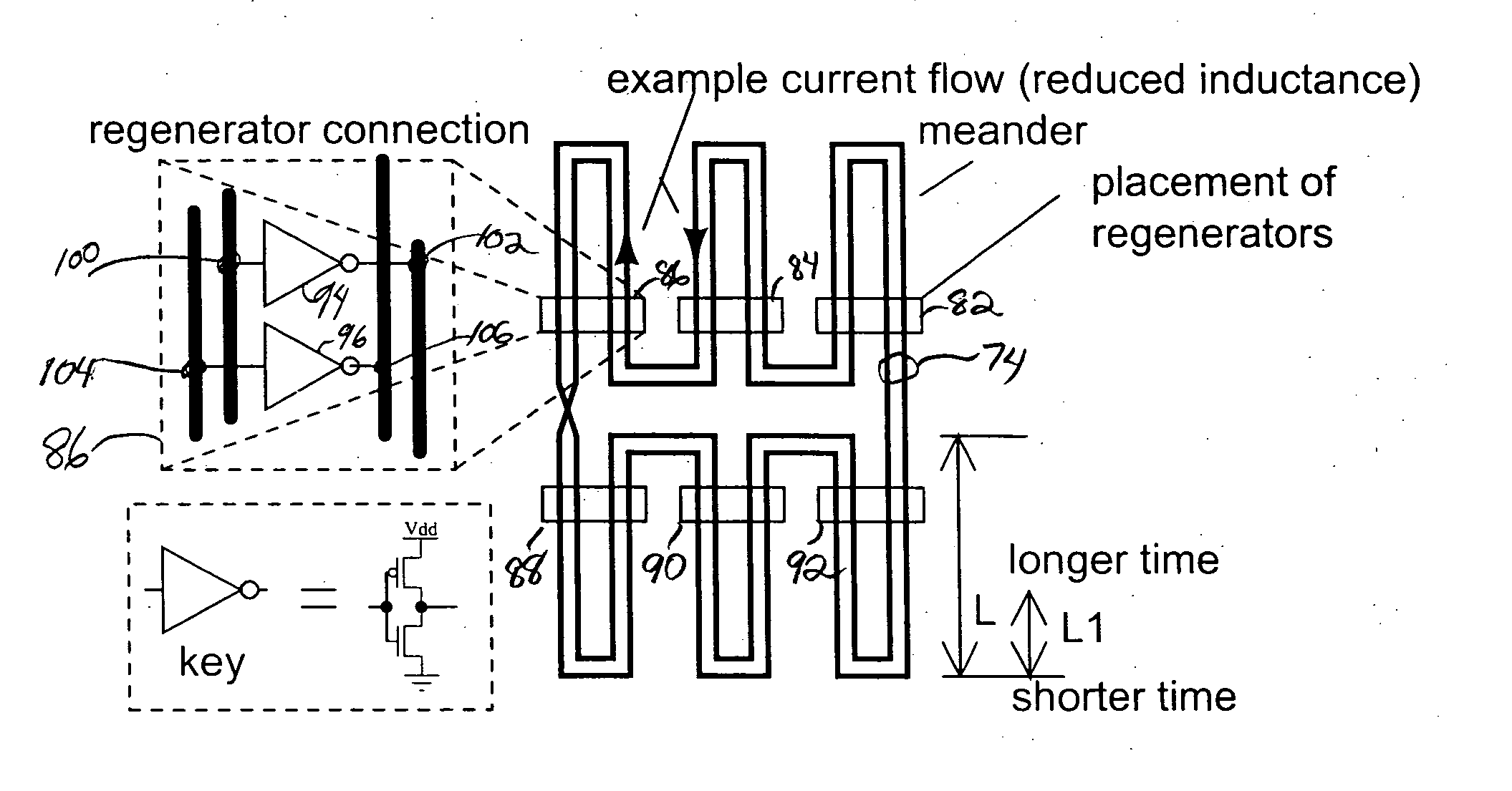
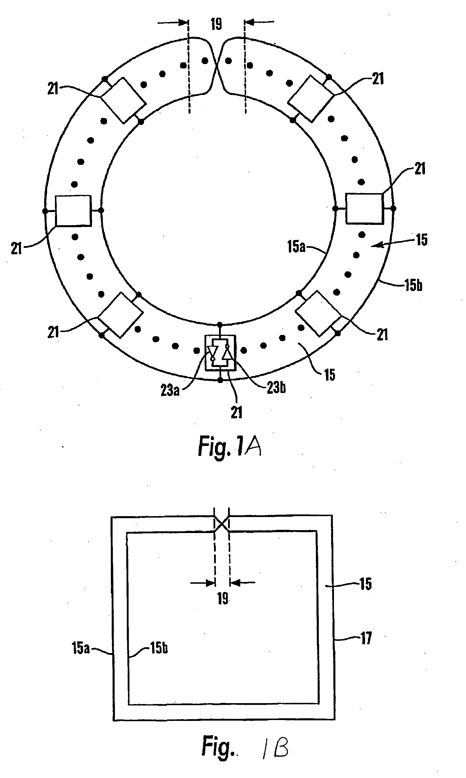
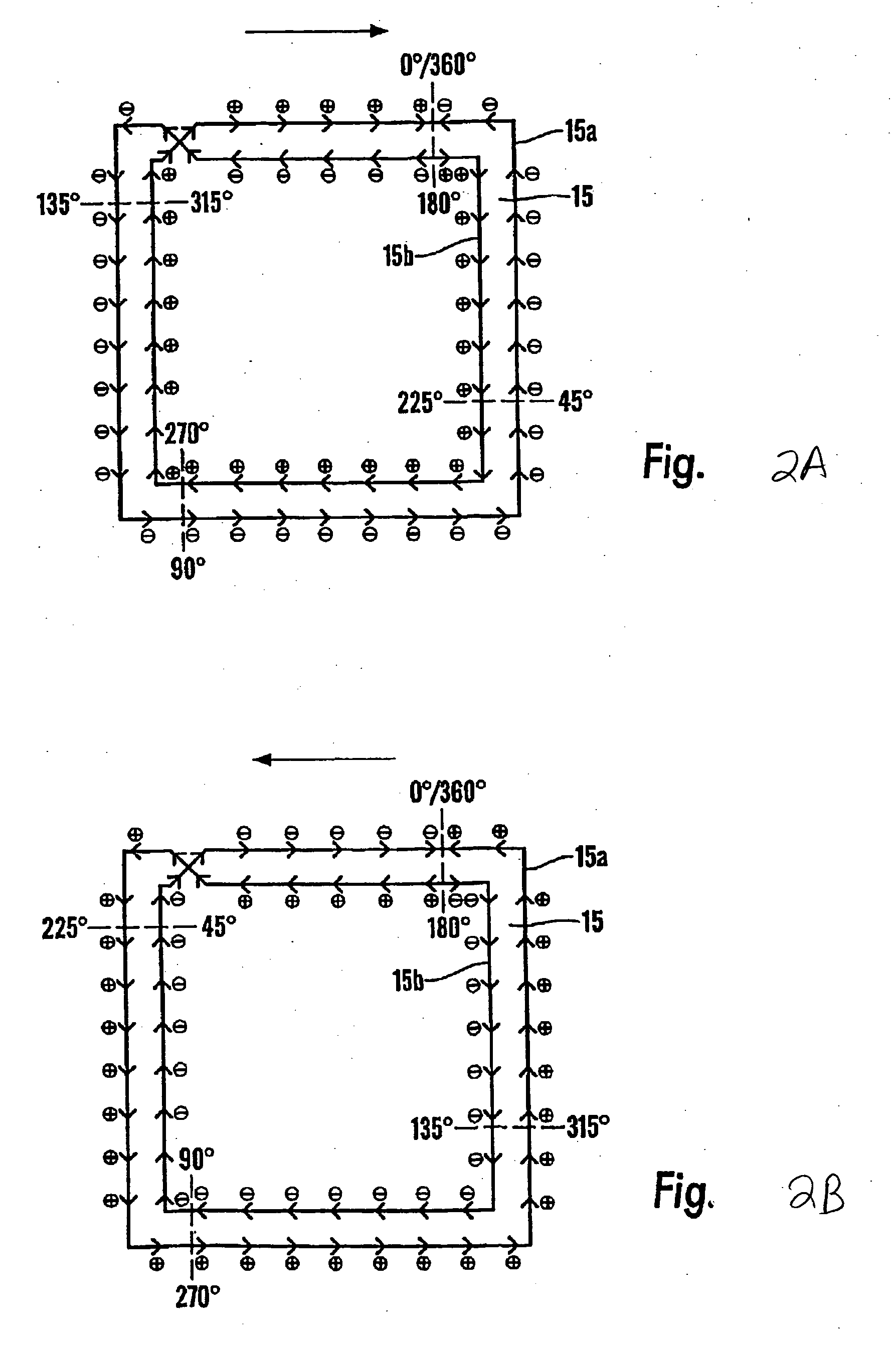
[0025]FIG. 1 shows a transmission-line 15 as a structure that is physically as well as electromagnetically endless, specifically comprising a single continuous “originating” conductor formation 17 shown forming two appropriately spaced generally parallel traces as loops 15a, 15b with a crossover at 19 that does not involve any local electrical connection of the conductor 17. The length of the originating conductor 17, taken as S, corresponds to two ‘laps’ of the transmission-line 15 as defined between the spaced loop traces 15a, 15b and through the cross-over 19. The crossover 19 produces a Moebius strip effect where edge traces of the loops 15a, 15b invert from lap to lap. Alternatively, the structure 15 can be viewed as one or more transmission line segments, where each segment has between its ends a length of spaced apart first and second conductors 15a, 15b. Each conductor is electrically continuous, meaning that there are no breaks in the conductors and no active elements in se...


PUM


Abstract

A low noise oscillator constructed using a rotary traveling wave oscillator. The conductors of the rotary traveling wave oscillator provide at any tap position a pair of oppositely phased oscillations and these oscillations have slightly different phases at positions that are slightly different on the conductors. Regeneration devices establish and maintain oscillations on the conductors of the traveling wave oscillator. A regeneration device made from p-channel and n-channel transistors is connected to the conductors of the traveling wave oscillator in such a way that the gate connections of the transistors receive the traveling wavefront before the drains of the transistors receive the wavefront. By the time the regeneration device switches in response to the wavefront arriving at the gates of the transistors, the wavefront has arrived at the drains. This creates little or no disturbance to the wave on the conductors and results in low phase noise.

Description

CROSS-REFERENCE TO RELATED APPLICATIONS [0001] This application is a continuation-in-part of pending U.S. application Ser. No. 10 / 275,461, filed Apr. 7, 2003, and titled “ELECTRONIC PULSE GENERATOR AND OSCILLATOR”, which application is incorporated by reference into the present application. [0002] This application claims the benefit of application Ser. No. 10 / 275,461, which is a national stage application of PCT application, PCT / GB01 / 02069, publication number WO 01 / 89088, filed May 11, 2001, and this application and the PCT / GB01 / 02069 application claim priority to GB0011243.3, filed May 11, 2000, GB0024522.2, filed Oct. 6, 2000, and GB0102700.2, filed Feb. 3, 2001. The PCT / GB01 / 02069, GB0011243.3, GB0024522.2, and GB0102700.2 are incorporated by reference into the present application.FIELD OF THE INVENTION [0003] The present invention relates generally to traveling wave oscillators and more specifically to traveling wave oscillators that achieve low levels of phase noise. DESCRIPTIO...

Claims


Application Information

Patent Timeline
Patent Type & Authority Applications(United States)
IPC IPC(8): H03K3/03H03K3/86
CPCH03B5/1852H01L2924/0002H01L2924/00
Inventor WOOD, JOHN
Owner ANALOG DEVICES INC
Why Eureka
Try Eureka