Head-mounted display system and method for processing images

a display system and display system technology, applied in static indicating devices, instruments, optical elements, etc., can solve the problems of user disorientation, predetermined time, and computation processing for generating images, and achieve the effect of reducing the time lag of image display and low cos

Inactive Publication Date: 2005-07-21
OLYMPUS CORP
View PDF4 Cites 87 Cited by
  • Summary
  • Abstract
  • Description
  • Claims
  • Application Information

AI Technical Summary

Benefits of technology

[0013] The head-mounted display system according to the present invention comprises: display means freely detachable and attachable on a user's head; direction-detecting means for detecting the orientation of a user's head in at least the horizontal direction, the direction-detecting means being disposed on the display means; an image generator for generating an image in accordance with the orientation of the user's head detected by the direction-detecting means; a displacement-calculating means for calculating displacement, the displacement being the difference between directional data of the current orientation of the user's head detected by the direction-detecting means and directional data of the orientation-of the user's head detected a predetermined amount of time ago; and image-processing means for sending an image generated at the image generator to the display means after shifting the image in at least the horizontal direction in accordance with the displacement calculated by the displacement-calculating means. According to this structure, the head-mounted display system according to the present invention can be produced at low cost and is capable of displaying an image, in real time, in accordance with the orientation of a user's head by reducing the time lag of image display caused by the arithmetic processing for generating an image.

Problems solved by technology

In reality, however, arithmetic processing for generating an image, carried out by the computer, requires a predetermined amount of time (Δt).
Since this type of delay is not experienced in the real world, this delay causes the user to experience a sense of disorientation.

Method used


Image

  • Head-mounted display system and method for processing images
  • Head-mounted display system and method for processing images
  • Head-mounted display system and method for processing images

Examples


first embodiment

[0025] (Configuration)

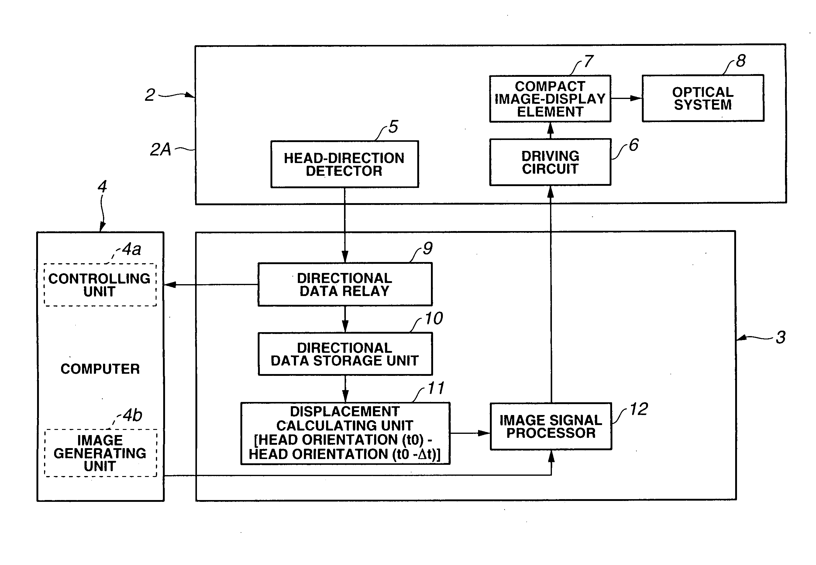
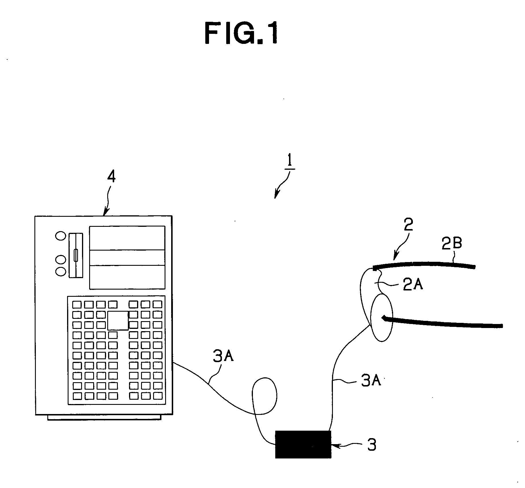
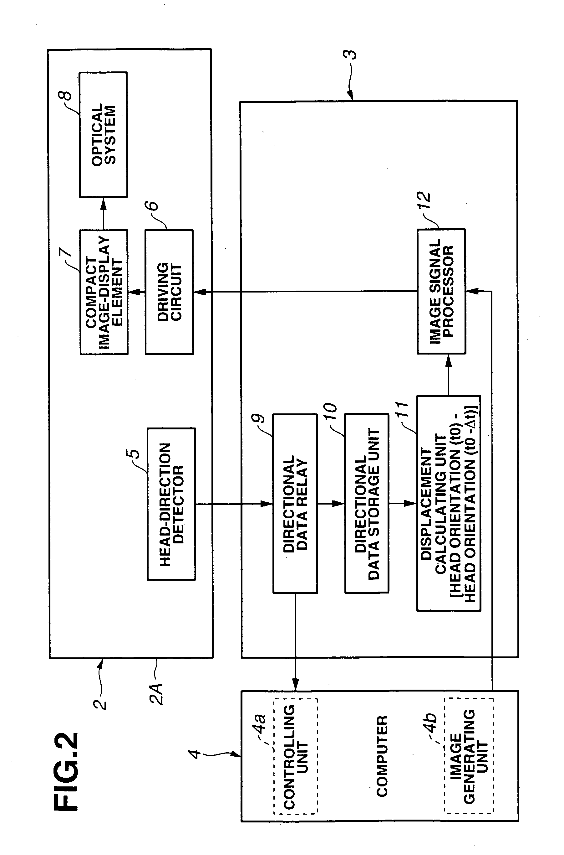
[0026] FIGS. 1 to 7 illustrate a first embodiment of the head-mounted display system according to the present invention. FIG. 1 illustrates the outline of the structure of the head-mounted display system. FIG. 2 is a block diagram illustrating the circuitry of the head-mounted display system. FIGS. 3 to 6 are schematic views illustrating the operating principle of the head-mounted display. FIG. 3 illustrates a displacement in directional data due to a time lag Δt. FIG. 4 illustrates a correction value Δθ for correcting the error due to the time lag Δt in the directional signal. FIG. 5 is a graph illustrating the correction value Δθ of FIG. 4 at time t. FIG. 6 illustrates the directional data for an image shifted in accordance with the correction value Δθ. FIGS. 7A to 7E illustrate the operation of the head-mounted display, wherein FIG. 7A illustrates time, FIG. 7B illustrates the orientations of a user's head, FIG. 7C illustrates the correct images viewed by a...

second embodiment

[0066] (Configuration and Operation)

[0067]FIG. 8 illustrates a head-mounted display system according to a second embodiment of the present invention and is a block diagram of the circuitry of the head-mounted display system. The components included in FIG. 8 that are the same as those of the first embodiment are represented by the same reference numerals. Only descriptions for components that differ from the first embodiment are provided.

[0068] According to the second embodiment, a Δt measuring unit 13 and a setup button 50 for automatically inputting Δt are provided in the controller 3. Moreover, the directional data relay 9 has an additional function. Other structures are the same as the head-mounted display system according to the first embodiment.

[0069] As illustrated in FIG. 8, the setup button 50 of the controller 3 is an operational button for automatically measuring Δt. When the setup button 50 is pressed down, an operational signal is sent to the directional data relay 9...

third embodiment

[0080] (Configuration and Operation)

[0081]FIG. 9 illustrates a third embodiment of the head-mounted display 1 according to the present invention and is a block diagram of the circuitry of the head-mounted display. The components included in FIG. 9 that are the same as those in the second embodiment are represented by the same reference numerals.

[0082] The head-mounted display system 1 according to the third embodiment includes first and second head-direction detecting units 5A and 5B instead of the head-direction detecting unit 5 according to the second embodiment. Furthermore, first and second directional data relays 9A and 9B corresponding to the first and second head-direction detecting units 5A and 5B are included instead of the directional data relay 9 according to the second embodiment.

[0083] More specifically, according to the third embodiment, a highly responsive acceleration sensor is used for measuring the directions required for the arithmetic processing carried out by...


PUM


Abstract

A head-mounted display system comprises: a display device freely detachable and attachable on a user's head; a direction detector for detecting the orientation of the user's head in at least the horizontal direction, the direction detector being disposed on the display device; an image generator for generating an image in accordance with the orientation of the user's head detected by the direction detector; a displacement-calculating unit for calculating displacement, the displacement being the difference between directional data of the current orientation of the user's head detected by the direction detector and directional data of the orientation of the user's head detected a predetermined amount of time ago; and an image processor for sending an image generated in the image generator to the display device after shifting the image in at least the horizontal direction in accordance with the displacement calculated by the displacement-calculating unit.

Description

CROSS REFERENCE TO RELATED APPLICATIONS [0001] This application is a continuation application of PCT / JP2003 / 010615 filed on Aug. 22, 2003, and claims benefit of Japanese Application Nos. 2002-255695 filed in Japan on Aug. 30, 2002 and 2003-290853 filed in Japan on Aug. 8, 2003, the entire contents of each of which are incorporated herein by their reference.BACKGROUND OF THE INVENTION [0002] 1. Field of the Invention [0003] The present invention relates to a head-mounted display system. More specifically, the invention relates to a head-mounted display system capable of displaying images in real time generated by an image generator based on the moving direction of a user's head without being affected by the processing time required for the arithmetic processing for generating the image, and also relates to a method for processing the images. [0004] 2. Description of the Related Art [0005] Systems including a head-mounted display (HMD) have been receiving great amount of attention rec...

Claims


Application Information

Patent Timeline
Patent Type & Authority Applications(United States)
IPC IPC(8): G02B27/00G02B27/01G06F3/00G06F3/01G06T15/20G09G5/00
CPCG02B27/0093G02B27/017G06T15/20G02B2027/0187G06F3/012G02B2027/014
Inventor IBA, YOICHI
Owner OLYMPUS CORP
Why Eureka
Try Eureka