
Alternative (reciprocating) engine with recirculation of exhaust gases intended for the propulsion of automobiles and method turbocharging these motors

a technology of automobiles and exhaust gases, which is applied in the direction of exhaust gas recirculation, non-fuel substance addition to fuel, lift valves, etc., can solve the problems of excessive exhaust gas enthalpy, insufficient exhaust temperature, and insufficient energy efficiency, so as to increase the proportion of egr and/or engine torque, eliminate the effect of power drop at high speed, and increase the supercharging pressur

Inactive Publication Date: 2007-11-29
MELCHIOR
View PDF33 Cites 12 Cited by
  • Summary
  • Abstract
  • Description
  • Claims
  • Application Information

AI Technical Summary

Benefits of technology

[0036] To increase the proportion of EGR and / or the engine torque by increasing the supercharging pressure by the mounting in series of two compressors with air cooling between the compressors, to eliminate the drop in power at high speed, to reduce the time lag for engagement of torque from idling and on engine pickup, to improve the combustion and the catalytic depollution after cold starting and at very lower power, to exploit the well-developed technology of waste gates by limiting the modes of operation with throttling of the gas flows, to reduce the volumetric ratio in order to comply with the maximum pressure permitted in the cylinder whilst retaining the capabilities on starting and on silent idling in cold weather, to extend the depolluted range of the field of use of the engine.

Problems solved by technology

These solutions with low energy efficiency are sufficient at moderate pressure where the enthalpy available in the exhaust gases is excessive.
When this fraction exceeds a limit, the exhaust temperature becomes insufficient to ensure the turbine / compressor energy balance.
These operations are carried out with poor energy efficiency due to the energy losses in the waste gate or in the variable distributor of the turbine.
Furthermore, the back pressure increases the engine consumption over the depolluted range of operation which is very much used in urban driving.
Moreover, the air pressure is limited as in the case of the single turbocharger.
In the two preceding cases certain transitions involve the acceleration of one of the rotors, which may prove too slow in the rapid transitions of urban driving.

Method used


Image

  • Alternative (reciprocating) engine with recirculation of exhaust gases intended for the propulsion of automobiles and method turbocharging these motors
  • Alternative (reciprocating) engine with recirculation of exhaust gases intended for the propulsion of automobiles and method turbocharging these motors
  • Alternative (reciprocating) engine with recirculation of exhaust gases intended for the propulsion of automobiles and method turbocharging these motors

Examples


Embodiment Construction

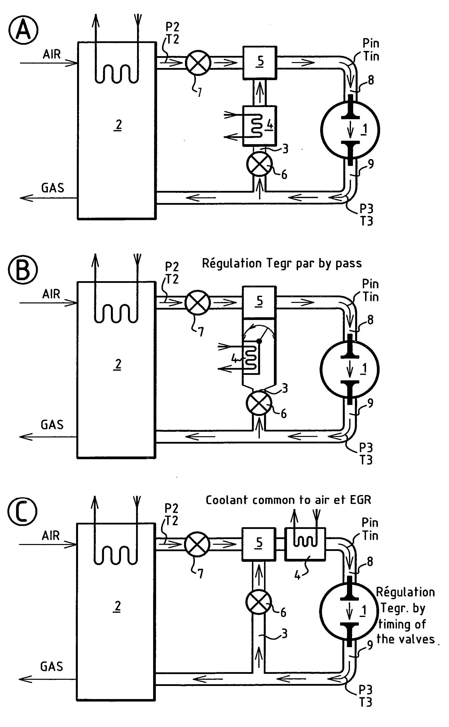
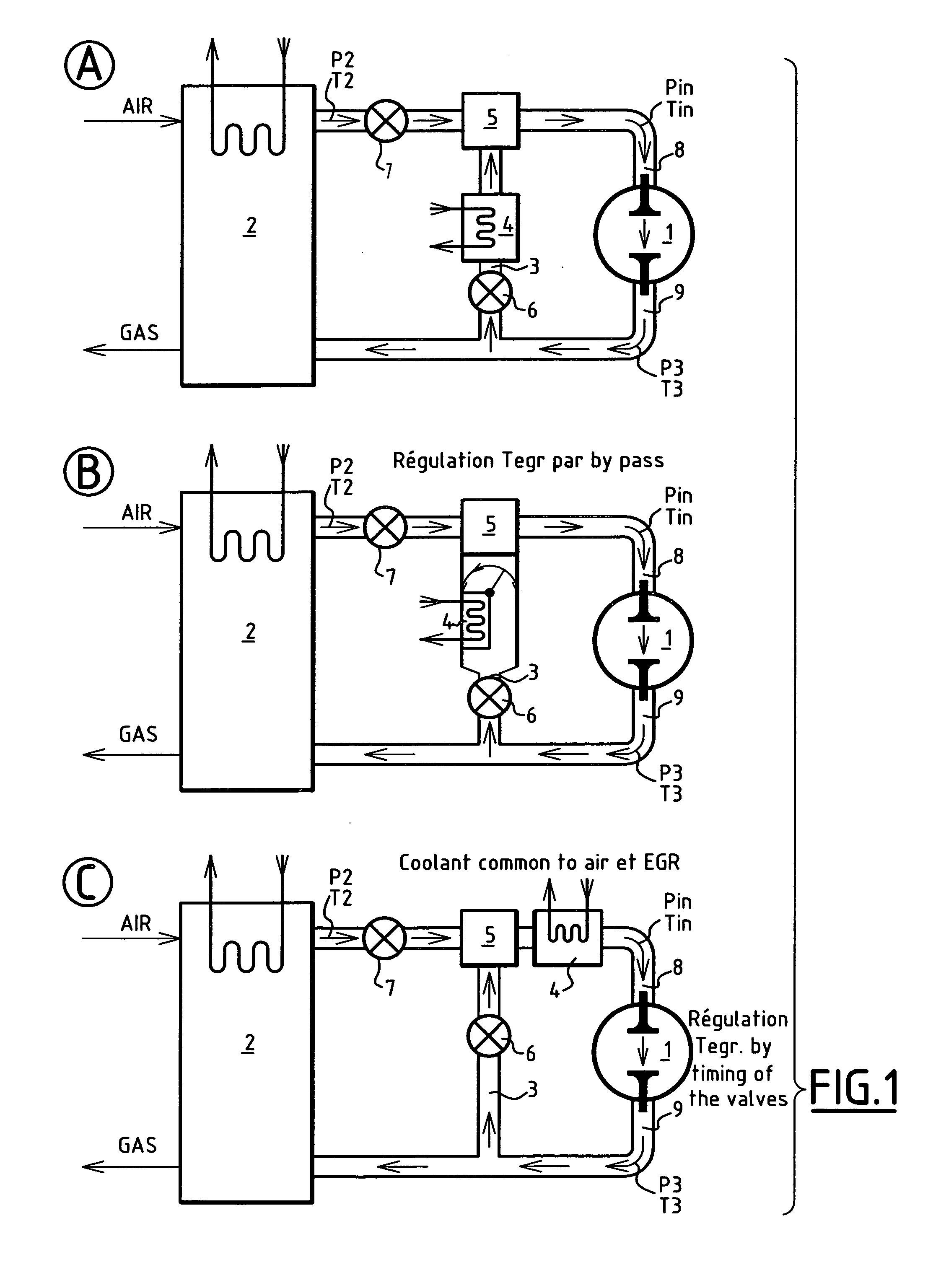
[0102] 1. The invention relates to a reciprocating engine used between a minimum speed of rotation Nmin and a maximum speed Nmax, which comprises a turbocharging unit dimensioned so as to function autonomously when: [0103] it supplies the intake manifold of the engine with air via a coolant [0104] it is supplied with gas by the exhaust manifold of the engine [0105] the turbine supply pressure P3 is substantially equal to the compressor discharge pressure P2.

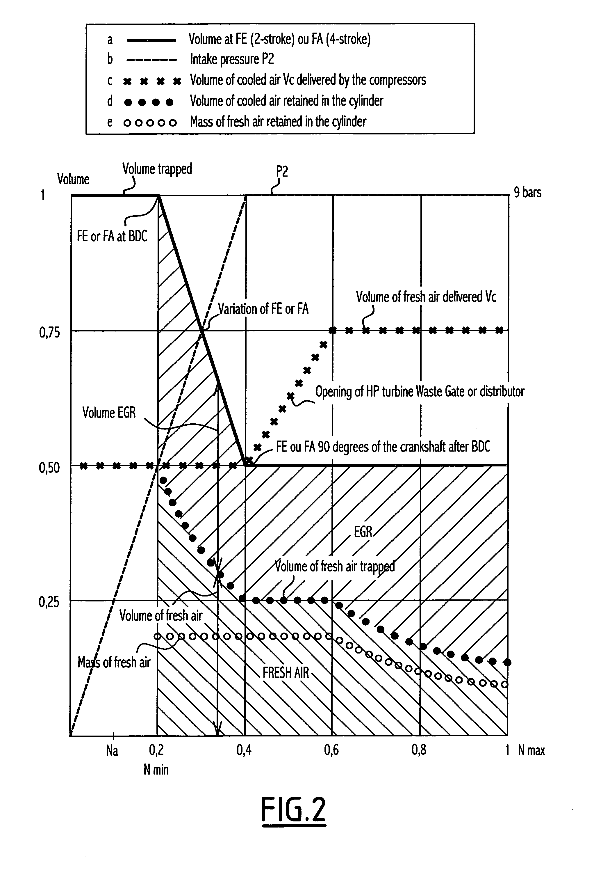
[0106] It is known that in these conditions, at constant air temperature and with a fixed geometry, the turbocharging delivers a substantially constant volume of cooled air Vc when the pressure varies.

[0107] It is also known that the volume Vc is substantially proportional to the turbine inlet section Sd offered to the hot gases.

[0108] In this engine according to the invention the turbine pressure P3 is maintained substantially equal to the compressor pressure by a bypass between the intake manifold and the exhaust manifold di...


PUM


Abstract

A reciprocating engine includes a turbocharging unit that: supplies the intake manifold with air via a coolant; is supplied with gas by the exhaust manifold; and has the turbine supply pressure substantially equal to the compressor discharge pressure. At constant air temperature, the turbocharging unit delivers a substantially constant volume of cooled air when the pressure varies, and the volume is substantially proportional to the turbine outlet section. The turbine pressure is maintained substantially equal to compressor pressure by a EGR bypass between the intake and exhaust manifold. In addition, the volume of air is less than the volume drawn in at the speed so that a flow of hot gases is drawn in again via the bypass above the speed, where the volume drawn in is equal to the volume, and a flow of air is deflected towards the turbine below the speed.

Description

BACKGROUND OF THE INVENTION [0001] 1. Field of the Invention [0002] In the past the thermodynamic cycles of automobile engines were optimised for thermal efficiency and specific power. [0003] Nowadays, added to the criteria of efficiency and specific power are the constraints of depollution and particularly the elimination of NOX. These constraints are currently limited to the conditions of urban use of the engine and to road journeys at low power. The foreseeable tightening up of the regulations will lead to an extension of the depolluted range of use of the engine. [0004] The depolluted range is currently limited to 50% of the maximum speed and 50% of the maximum torque, the engine being supplied with fresh air within the range of the raised torques and power. [0005] Numerous techniques for depollution by post-treatment of the gases discharged into the atmosphere are used or are in the course of development, such as oxidoreduction catalysts and regeneratable filters for particles ...

Claims


Application Information

Patent Timeline
Patent Type & Authority Applications(United States)
IPC IPC(8): F02B33/44F01L1/34F01L1/46F02B37/013F02B37/18F02B37/24F02M25/07
CPCF01L1/34F02B37/004F01L2800/00F02B29/0425F02B29/0437F02B29/0475F02B37/013F02B37/02F02B37/18F02B37/183F02B37/24F02M25/0707F02M25/0711F02M25/0713F02M25/0728F02M25/0731F02M25/0735Y02T10/121Y02T10/146Y02T10/144F01L1/46F02M26/05F02M26/08F02M26/10F02M26/25F02M26/28F02M26/30Y02T10/12
Inventor MELCHIOR, JEAN FREDERIC
Owner MELCHIOR
Learn More