
Input control apparatus and method for responding to input

Inactive Publication Date: 2005-07-21
ALPINE ELECTRONICS INC
View PDF4 Cites 37 Cited by
  • Summary
  • Abstract
  • Description
  • Claims
  • Application Information

AI Technical Summary

Benefits of technology

[0009] Accordingly, an object of the present invention is enabling a user to perform an operation according to the user's intention more reliably in a user interface using a touch panel disposed on a screen of a display device.
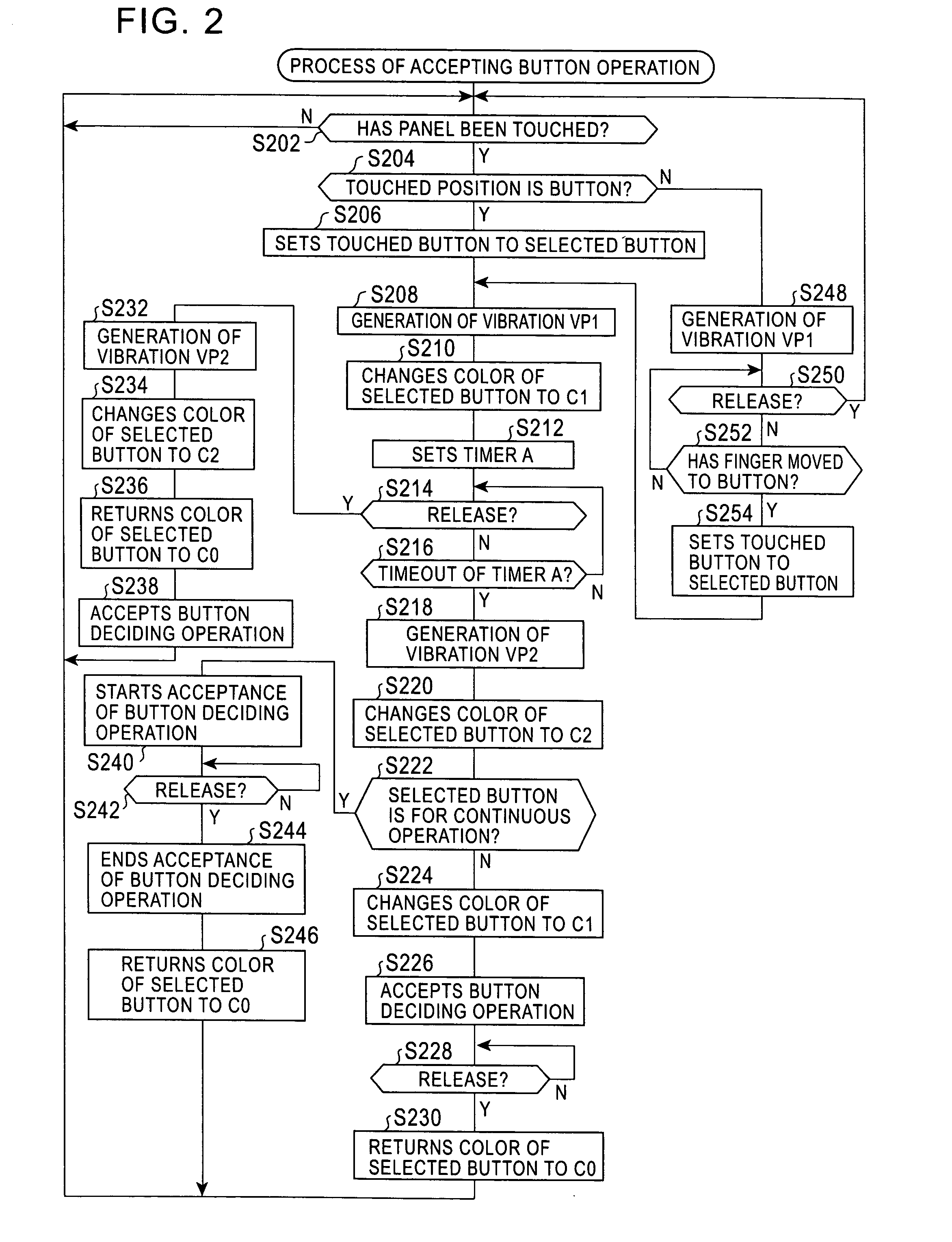
[0011] In this input control apparatus, when a user's touch on an area outside of the buttons is detected, the detection of touch is notified to the user by generating vibration. Therefore, the user can determine whether his / her way of touching is appropriate by touching an area outside the buttons, that is, an area which is irrelevant to the operation. Further, after the user has touched a position outside of the buttons, when the user moves his / her finger along the touch panel in order to touch a desired button, vibration indicating that the touched position is within the range of the button is given to the user. Accordingly, the user can simultaneously perform a determination of the appropriateness of his / her way of touching and movement of the touched position to the desired button reliably by performing a sequential operation of moving his / her finger from the outside of the buttons to the desired button.
[0014] Preferably, the screen display unit changes the color of the button corresponding to the touched position so that the user can distinguish the button from other buttons. With this configuration, the user can touch a desired button or move the touched position to the desired button more reliably.
[0017] According to the present invention, in a user interface using a touch panel disposed on a screen of a display device, the user can perform an operation according to his / her intention more easily and reliably.

Problems solved by technology

Furthermore, in these techniques, when the user performs touch and release operations on the touch panel, if the touched position just before the release operation is different from the position of the button corresponding to the touched position at the touch operation, selection of the released button is not accepted (e.g., Patent Document 3).
For this reason, even when a user touches a proper operating position on a touch panel, the touch panel may not be able to detect the touch and accept the operation according to the user's intention, depending on the user's operation or user's status.

Method used


Image

  • Input control apparatus and method for responding to input
  • Input control apparatus and method for responding to input
  • Input control apparatus and method for responding to input

Examples


Embodiment Construction

[0022] Hereinafter, an embodiment of the present invention will be described.

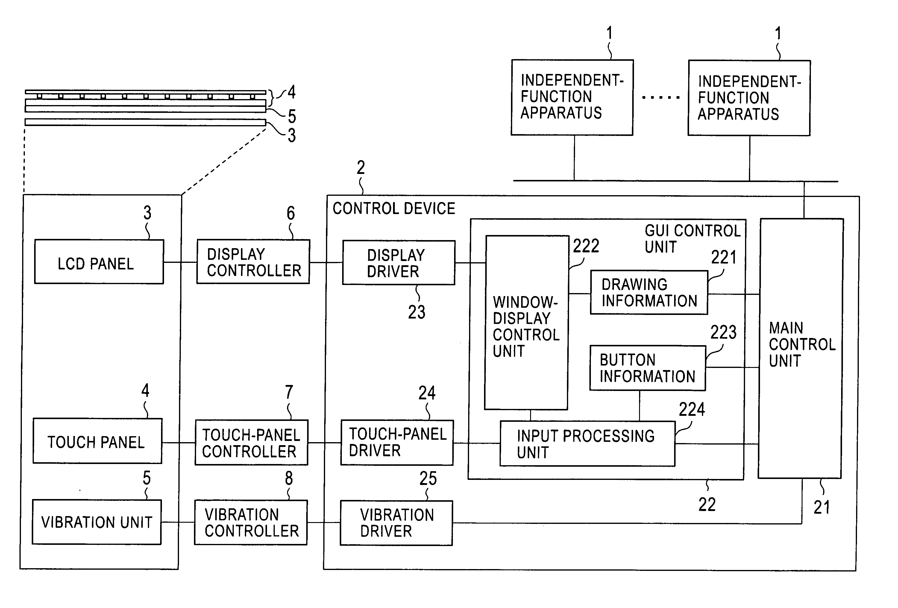
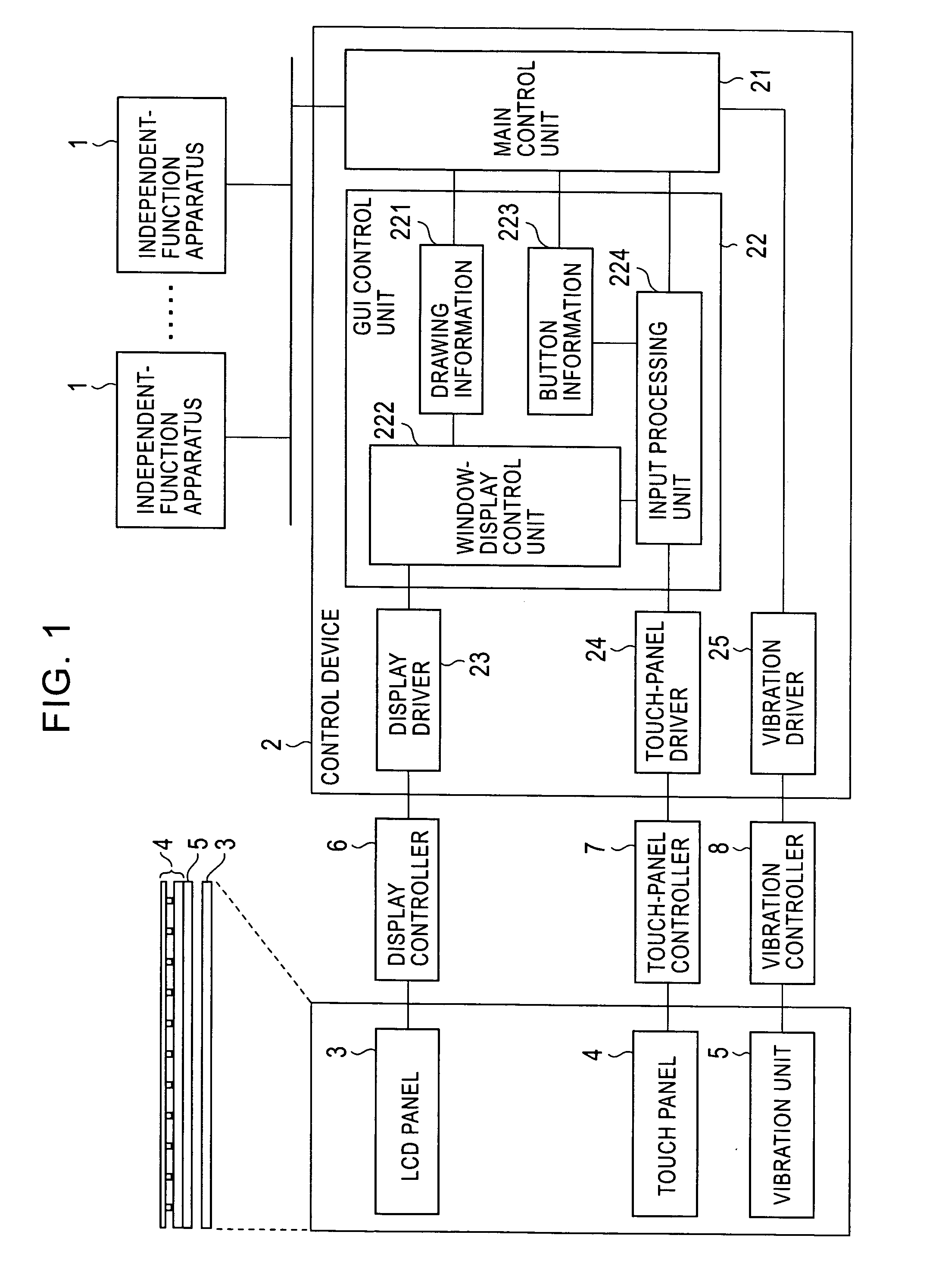
[0023]FIG. 1 shows the configuration of an electronic processing system according to the embodiment.

[0024] As shown in FIG. 1, the electronic processing system includes independent-function apparatuses 1 having an independent function, such as an audio apparatus and a navigation apparatus; a control device 2 for controlling each of the independent-function apparatuses 1; a liquid crystal display (LCD) panel 3; a touch panel 4; a vibration unit 5; a display controller 6 for driving the LCD panel 3; a touch-panel controller 7 for detecting occurrence of touch / release operations on the touch panel 4 and touched coordinates (coordinates of a touched position); and a vibration controller 8 for driving the vibration unit 5.

[0025] As shown in FIG. 1, the vibration unit 5 is disposed under the touch panel 4 so as to be coupled therewith and vibrates the touch panel 4. The LCD panel 3 is disposed under the touch ...


PUM


Abstract

In a menu window, when a user touches an area outside buttons on a touch panel, a main control unit vibrates the touch panel by using a first vibration pattern. When the user moves his / her finger along the touch panel so as to reach the range of coordinates of one of the buttons, the main control unit generates the first vibration pattern which indicates the acceptance of an operation of selecting the button and changes the color of the button to a color indicating a button selected state when the touched position reaches the range of the button. Then, the main control unit accepts an operation of deciding the button according to a release operation or long touch performed thereafter.

Description

BACKGROUND OF THE INVENTION [0001] 1. Field of the Invention [0002] The present invention relates to a user interface including a display device and a touch panel disposed on a screen of the display device. [0003] 2. Description of the Related Art [0004] As a technique related to a user interface using a touch panel disposed on a screen of a display device, the following technique has been known. That is, a vibrator for vibrating a touch panel is provided, a user's operation of touching an area of the touch panel corresponding to a button displayed on a display device is accepted as a button touching operation, and a response to the touch operation is fed back to the user by using vibration of the touch panel (e.g., Patent Documents 1 and 2: Japanese Unexamined Patent Application Publication Nos. 2003-16502 and 2000-137576). [0005] Also, as another technique related to a user interface using a touch panel disposed on a screen of a display device, the following technique has been kno...

Claims


Application Information

Patent Timeline
IPC IPC(8): G06F3/00G06F3/01B60R16/02G06F3/041H01H3/50H01H9/16H01H36/00
CPCG06F3/016
Inventor KATAYOSE, JUN
Owner ALPINE ELECTRONICS INC
Learn More