
Inkjet print head

a print head and inkjet technology, applied in the direction of printing, inking apparatus, etc., can solve the problems of reducing the overall stability of the ink-jet operation and shortening the life of the heater b, and achieve the effect of increasing the stability of the ink-jet operation and prolonging the life of the print head

Inactive Publication Date: 2005-07-21
INT UNITED TECH
View PDF4 Cites 6 Cited by
  • Summary
  • Abstract
  • Description
  • Claims
  • Application Information

AI Technical Summary

Benefits of technology

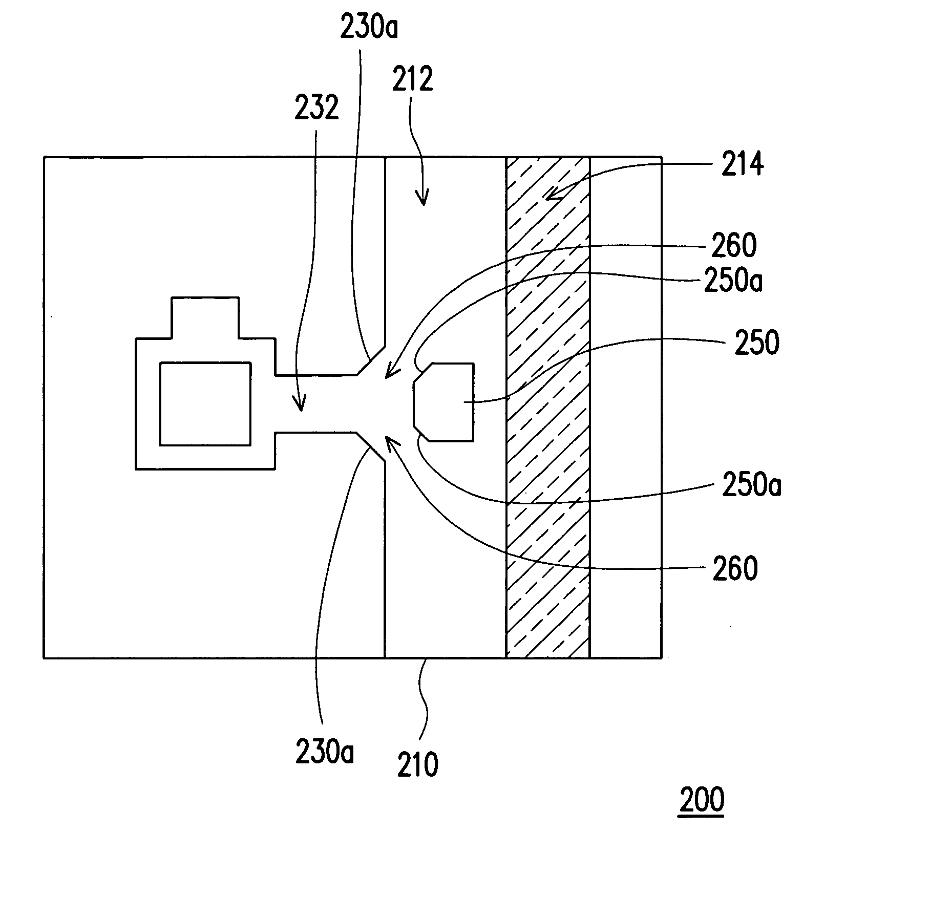
[0010] Accordingly, the present invention is related to an inkjet print head capable of collecting, holding and / or isolating air bubbles and / or impurities left after an ink-jetting operation for increasing jetting stability and extending the life of print head.
[0011] According to an embodiment of the present invention, the inkjet print head is capable of increasing refilling frequency and drop volume during a printing operation.
[0018] In one embodiment of the present invention, the chamber layer (or the nozzle plate) further comprises a pair of first ink-channeling surfaces. One first ink-channeling surface is formed on the first side of the first ink channel, and the other first ink-channeling surface is formed on the other side of the first ink channel. The surface of the ink chip further includes an island (or a block). The island has a pair of second ink-channeling surfaces. The island is formed between the first ink channel and the ink slot. The first ink-channeling surfaces and the second ink-channeling surfaces together form a pair of second ink channels joined to the first ink channel. The first ink-channeling surfaces and their corresponding second ink-channeling surfaces can be parallel to each other. By placing an island on the ink chip, two separate second ink channels merge into the first ink channel. Hence, ink refilling frequency and jetting stability of the ink jet printer during printing operation is improved.
[0019] In the embodiment of the present invention, if the first ink channel, the ink chamber and the nozzles are fabricated together on a nozzle plate, the nozzle plate further comprises a projection protruding from the bottom surface of the nozzle plate. The projection is located between the first ink channel and the ink slot, and can be have a distance from the surface of the ink chip. In addition, the projection on the nozzle plate has a pair of second ink-channeling surfaces. The first ink-channeling surfaces formed on the sides of the first ink channel and the second ink-channeling surfaces together form a pair of second ink channels that join to the first ink channel, which can improve the ink refilling frequency and jetting stability of the ink jet printer during operation.
[0020] In one embodiment of the present invention, the chamber walls of the ink chamber within the inkjet print head has a distance offset between two areas formed on the chamber wall so that at least one collecting room is formed. Consequently, any air bubbles and / or impurities generated after an ink-jetting operation is collected inside the collecting room. With this design, the inkjet print head can have a higher jetting stability and a longer life. Furthermore, by forming an island in front of or within the ink channel that leads to the ink chamber, two ink channels capable of increasing the ink refilling frequency and ink drop volume of the ink jet printer are formed.

Problems solved by technology

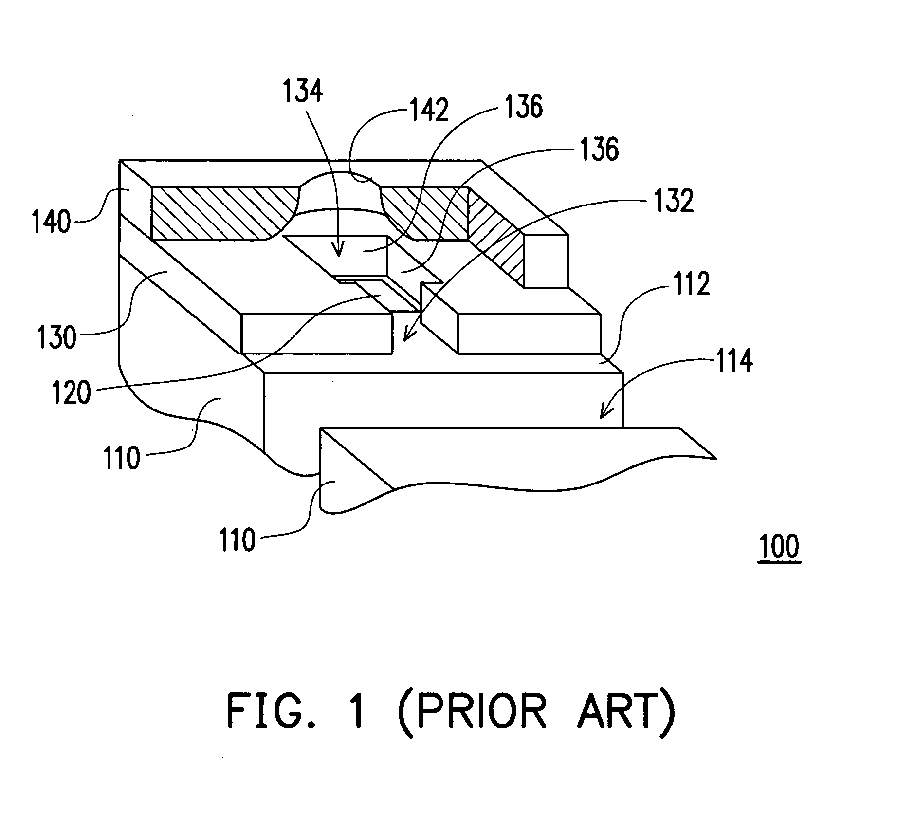
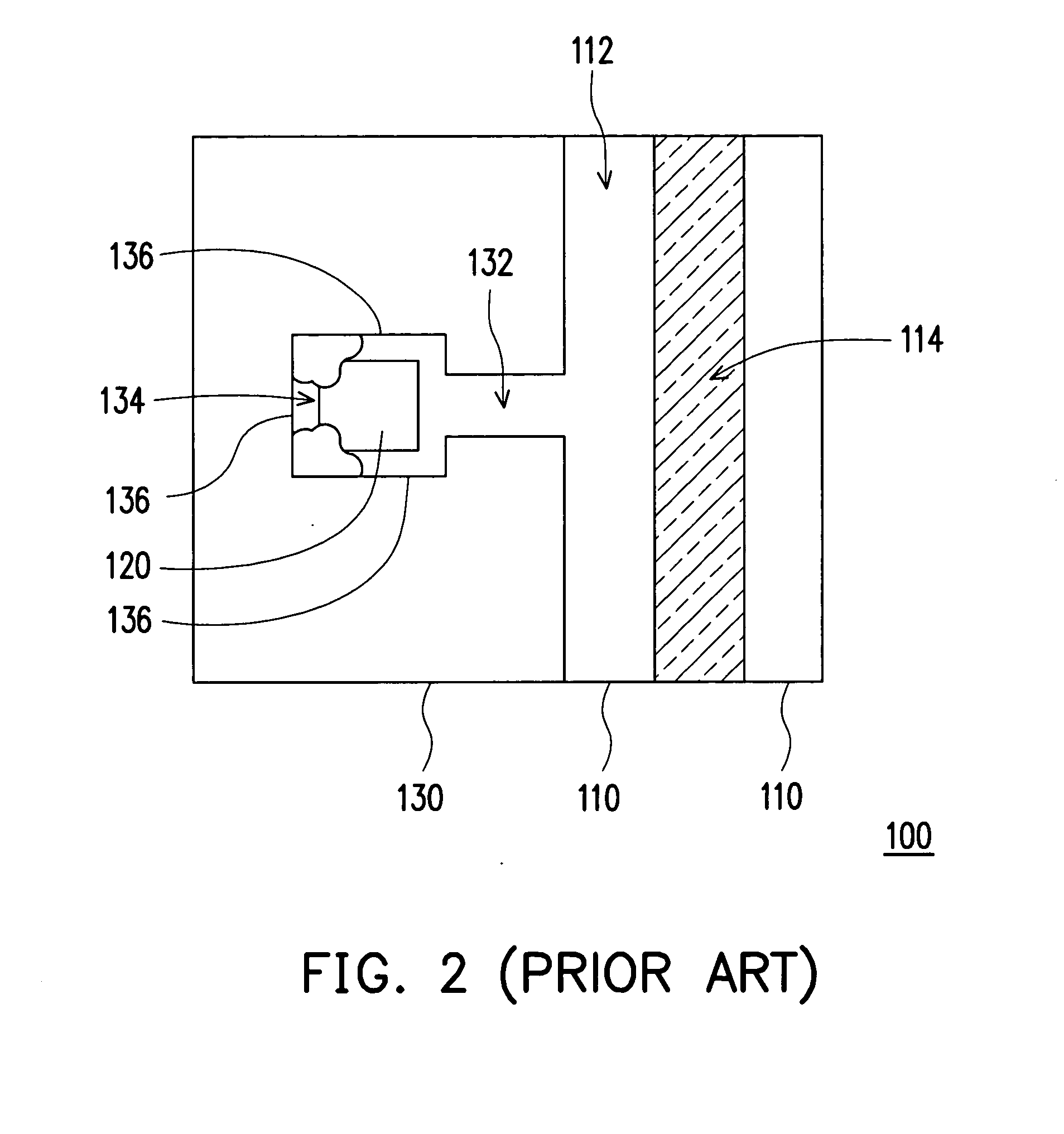
Empty heating in part of the heater 120 not only shortens the life of the heater 120 but also reduce overall stability of the ink-jetting operation.

Method used


Image

  • Inkjet print head
  • Inkjet print head
  • Inkjet print head

Examples


Embodiment Construction

[0034] Reference will now be made in detail to the present preferred embodiments of the invention, examples of which are illustrated in the accompanying drawings. Wherever possible, the same reference numbers are used in the drawings and the description to refer to the same or like parts.

[0035]FIG. 4 is a perspective view of an inkjet print head according to one embodiment of the present invention. FIG. 5 is a top view of the inkjet print head in FIG. 4. As shown in FIGS. 4 and 5, the inkjet print head 200 comprises an ink chip 210, a plurality of heaters 220 (only one is shown), a chamber layer 230 and a nozzle plate 240. For the sake of simplification, the nozzle plate 240 in FIG. 4 is omitted in FIG. 5. The ink chip 210 has a surface 212 and at least an ink slot 214. The ink slot 214 has an elongated shape (other suitable shape may be used, for example, an elliptical or a circular shape) and is formed through the ink chip 210. The heaters 220 and the chamber layer 230 are formed...


PUM


Abstract

An inkjet print head comprising an ink chip, at least a heater, a chamber layer and a nozzle plate is provided. The heater and the chamber layer are formed on the surface of the ink chip. The chamber layer has at least an ink channel and at least an ink chamber. The ink chamber exposes the heater and connects to a reservoir through the ink channel. The ink chamber has a plurality of chamber walls. At least one of the chamber walls has a first area and a second area. The first area corresponds to the heater. The first area and the second area have a distance offset for forming at least a collecting room. The nozzle plate is positioned over the chamber layer. The nozzle plate has at least a nozzle positioned above the heater. By forming the collecting room, air bubbles and / or impurities within the ink can be collected after an ink-jetting operation.

Description

CROSS-REFERENCE TO RELATED APPLICATION [0001] This application claims the priority benefit of Taiwan application serial no. 93201151, filed on Jan. 20, 2004. BACKGROUND OF THE INVENTION [0002] 1. Field of the Invention [0003] The present invention relates to an inkjet print head. More particularly, the present invention relates to a thermal bubble ink jet print head capable of collecting, holding and / or isolating any air bubbles and / or impurities within the ink or generated after an ink-jetting operation. [0004] 2. Description of Related Art [0005] With the rapid development in the electronic industry, many high-tech products are produced in recent years. In particular, there is a major revolution in the design of printers, from the pin-activated and monochromatic laser printing to color inkjet and color laser printing. The two major methods used by a conventional inkjet printer for producing ink jets are the piezoelectric and thermal bubble techniques. One major aspect of the techn...

Claims


Application Information

Patent Timeline
Patent Type & Authority Applications(United States)
IPC IPC(8): B41J2/14
CPCB41J2/1404B41J2002/14387B41J2202/11B41J2202/07B41J2002/14403
Inventor LEE, CHEE-SHUENHU, JUI-HUACHEN, JIA-LIN
Owner INT UNITED TECH
Learn More