Communication channel structure and method

a communication channel and channel structure technology, applied in the field of telecommunication systems, can solve the problems of unacceptably slow services, poor voice service delivery medium, low error rate, etc., and achieve the effects of improving the utilization balance of at least two uplink channels, reducing the number of downlink channels, and monitoring the utilization level

Inactive Publication Date: 2005-07-21
WI LAN INC
View PDF2 Cites 82 Cited by
  • Summary
  • Abstract
  • Description
  • Claims
  • Application Information

AI Technical Summary

Benefits of technology

[0033] Preferably, the base station includes at least two uplink channels and associated downlink control channels and further including the step of assigning each of the at least two subscriber stations to use a different one of the at least two uplink channels and the associated downlink control channel and wherein steps (i) through (v) are performed for each of the at least two uplink channels. Also preferably, at least one of said at least two uplink channels has greater transmission capacity than another of the at least two uplink chan...

Problems solved by technology

More recently, attempts have been made to offer data services (i:e. such as web-browsing) over existing cellular digital telephone networks, but in general these services are unacceptably slow, because such services have different requirements than voice communications.
Specifically, while data services can accommodate relatively high latencies, they generally require low error rates.
This optimization has lead to the result that the Internet is a poor medium for carrying voice services.
To date however, the expectations of 3G have not been met, as the challenges of providing such networks have proven more greater than expected.
As will be apparent to those of skill in the art, as is the case with all random access techniques, as more subscriber stations attempt to access the CPCH,...

Method used


Image

  • Communication channel structure and method
  • Communication channel structure and method
  • Communication channel structure and method

Examples


Embodiment Construction

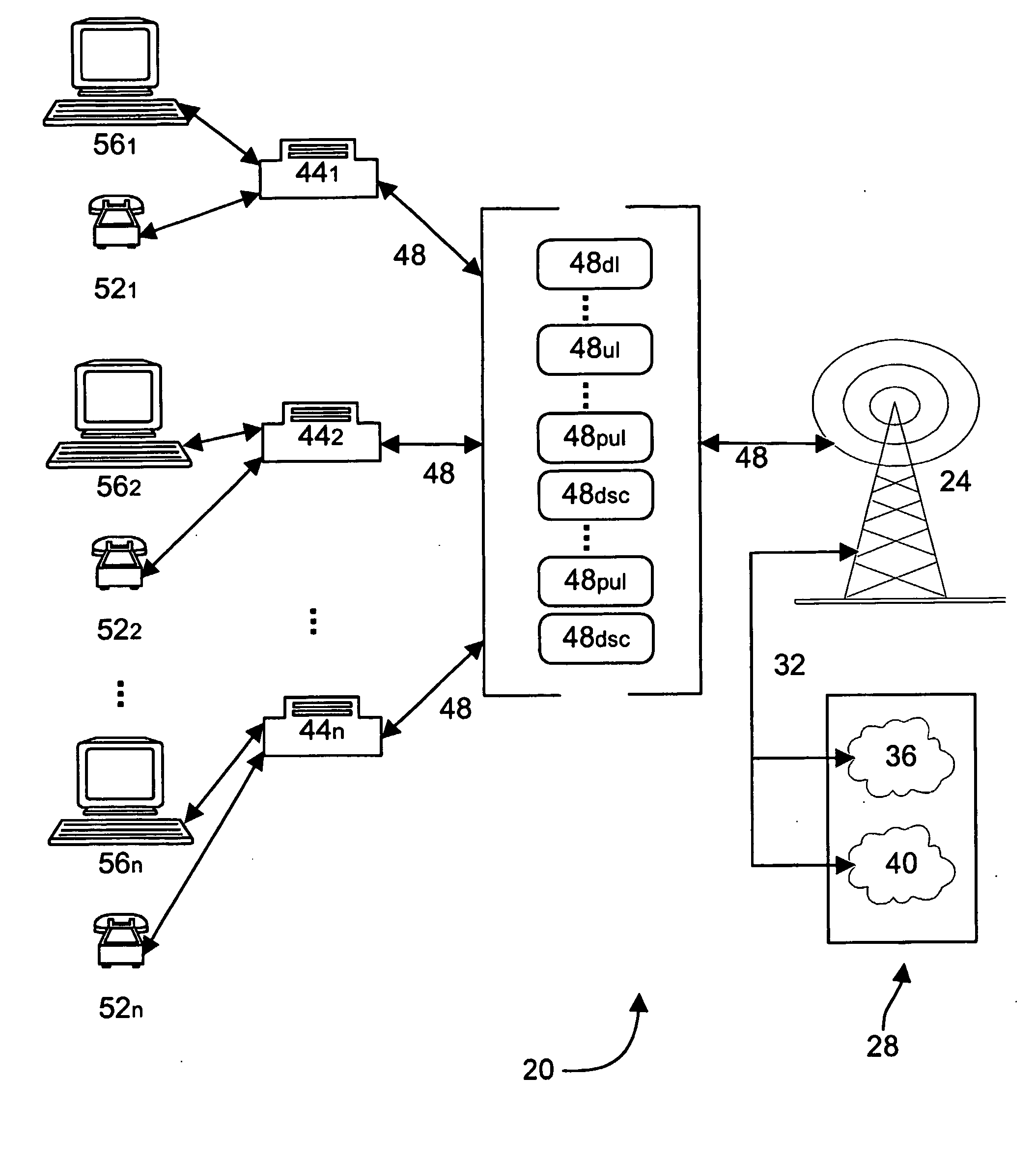
[0049] Referring now to FIG. 1, a wireless local loop system is indicated generally at 20. System 20 includes a wireless base station 24 that connects, through appropriate gateways, to a communication network 28 via a backhaul 32. Network 28 can be operable to carry different types of communication services, which in the present embodiment includes both data to and from public switched telephone network (PSTN) 36 and data to and from a packet switched data network 40, such as the Internet, although network 28 can also be a converged network, etc. as will be apparent to those of skill in the art. Backhaul 32 can be any known type of suitable backhaul link between wireless base station 24 and network 28, such as a T1, T3, OC1 or a wireless microwave link, etc.

[0050] Base station 24 has a transceiver that is used for communicating with a plurality of subscriber stations 441 through 44n via a wireless link 48. In a present embodiment, wireless link 48 employs CDMA as a multiple access ...


PUM


Abstract

A novel communication channel structure and method in a wireless communication system is provided. In an embodiment of the invention, the communication system includes a base station and a plurality of subscriber stations and the subscriber stations are given access to a variety of channels, including at least one uplink data channel. The uplink data channel can operate in at least a random access mode and a polled access mode. The base station informs each subscriber station it serves of the current mode of the uplink channel via an associated downlink signaling channel and, in random access mode, each subscriber station is able to randomly access the shared uplink channel. In polled mode, each subscriber station waits for permission from the base station before sending data over the shared uplink channel. A method of operating the system monitors the collisions which occur on the uplink channel in random mode and/or the amount of data and/or the data's priority level and/or QoS requirements and switches the system between random and polled modes as appropriate. In polled mode, the method determines which subscriber stations should access the uplink and when.

Description

FIELD OF THE INVENTION [0001] The present invention relates telecommunication systems that carry data, voice and / or other services over a communication link, and more particularly relates to a channel structure and method for operating such communication links. BACKGROUND OF THE INVENTION [0002] Telecommunication services have undergone tremendous advancement in the last decade. As an example, wireless or cellular telephone systems have now become largely ubiquitous. The advancement from analog cellular telephones, to more sophisticated digital telephones that utilize multiple access techniques such as CDMA or GSM has been very rapid. [0003] Cellular digital telephone networks have been engineered primarily to carry voice communications, meaning the connections provided have a fixed maximum data rate, a low latency (as voice communication is sensitive to latency) and the connections can tolerate relatively high error rates (as voice communication can tolerate such error rates). [000...

Claims


Application Information

Patent Timeline
IPC IPC(8): H04L47/43H04W28/12H04L12/28H04W74/02
CPCH04W74/02
Inventor MANTHA, RAMESHCASTURA, JEFFREY P.
Owner WI LAN INC
Why Eureka
Try Eureka