Single mode optical fiber with ultralow loss and large effective area and manufacturing method thereof
A single-mode fiber, effective area technology, used in cladding fibers, manufacturing tools, glass manufacturing equipment, etc., can solve problems affecting fiber strength and service life, affecting fiber transmission loss reduction, and difficulty in realizing low-loss fibers. Achieve the effects of superior bending resistance, increased effective area, and ultra-low loss effective area
- Summary
- Abstract
- Description
- Claims
- Application Information
AI Technical Summary
Problems solved by technology
Method used
Image
Examples
Embodiment 1
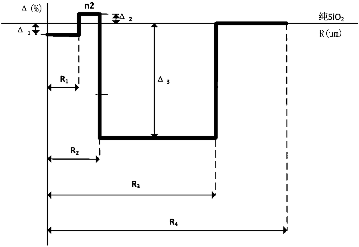
[0047] see figure 1 and figure 2 As shown, the embodiment of the present invention provides a single-mode optical fiber with ultra-low loss and large effective area. The bare optical fiber includes a core layer and a cladding layer from the inside to the outside in sequence, and the core layer includes an inner core layer 1 and a cladding layer that are sequentially arranged from the inside to the outside. Radius R of outer core layer 2 and inner core layer 1 1 1.5-3μm, the relative refractive index difference Δ of the inner core layer 1 1 -0.01%≤Δ 1 ≤0, the radius R of the outer core layer 2 2 5-6 μm, the relative refractive index difference Δ of the outer core layer 2 2 0≤Δ 2 ≤0.05%; the core layer is hardly doped with germanium, and the core layer is a silica glass layer co-doped with fluorine and alkali metal oxides; the cladding layer includes a sunken cladding layer 3 and an outer cladding layer 4 arranged sequentially from the inside to the outside, and the sunken...
Embodiment 2
[0066] This embodiment provides a method for manufacturing the above-mentioned ultra-low loss and large effective area single-mode optical fiber, which includes the following steps: using plasma chemical vapor deposition to deposit on a quartz reaction tube to make an optical fiber preform, and the optical fiber preform is made of SiCl 4 、GeCl 4 、C 2 f 6 As the raw material, the designed optical rod profile is prepared by changing the gas flow rate and ratio, as well as the moving speed of the reaction zone and the number of deposition times during the production process, and a certain concentration of alkali metal oxide is added during the rod forming process, and oxygen is introduced at the same time The reaction is carried out to remove water, and finally the high temperature is melted and shrunk into a rod to prepare an alkali metal-doped optical fiber preform rod, and the alkali metal-doped optical fiber preform rod is subjected to wire drawing treatment.
[0067] Where...
Embodiment 3~7
[0071] In the present invention, the PCVD deposition method is used to effectively control the distribution of the refractive index of each layer. The following five specific examples of Examples 3-7 are used to illustrate.
[0072] Table 1. Refractive index profile and doping material content of the single-mode optical fiber of the present invention
[0073]
[0074]
[0075] Table 2, the main performance parameters of the single-mode optical fiber of the present invention
[0076]
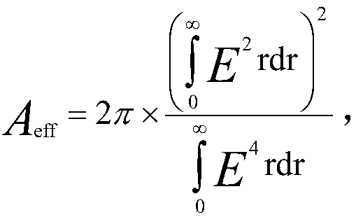
[0077] As can be seen from the above Table 2, the single-mode optical fiber provided by the present invention has a mode field diameter of 12.1-13um at a working wavelength of 1550nm, which can not only reduce the power density of light, but also increase the effective area of the optical fiber. Area higher than 122um 2 , even up to 130um 2 about.
[0078] In the single-mode optical fiber provided by the present invention, the radius R of the inner core layer 1 1 1.5-3 μm, the radi...
PUM
| Property | Measurement | Unit |
|---|---|---|
| radius | aaaaa | aaaaa |
| radius | aaaaa | aaaaa |
| refractive index | aaaaa | aaaaa |
Abstract
Description
Claims
Application Information
 - R&D
- Intellectual Property
- Life Sciences
- Materials
- Tech Scout
- Unparalleled Data Quality
- Higher Quality Content
- 60% Fewer Hallucinations
Browse by: Latest US Patents, China's latest patents, Technical Efficacy Thesaurus, Application Domain, Technology Topic, Popular Technical Reports.
© 2025 PatSnap. All rights reserved.Legal|Privacy policy|Modern Slavery Act Transparency Statement|Sitemap|About US| Contact US: help@patsnap.com


