

Moving picture coding method and moving picture coding apparatus
a coding method and coding apparatus technology, applied in the field of moving picture coding method and moving picture coding apparatus, can solve the problems of increasing calculation amount and hardware scale, reducing the processing load, and reducing the rate distortion-wise optimizing method, so as to achieve the effect of increasing the processing load
- Summary
- Abstract
- Description
- Claims
- Application Information
AI Technical Summary
Benefits of technology
Problems solved by technology
Method used
Image

Examples
first embodiment
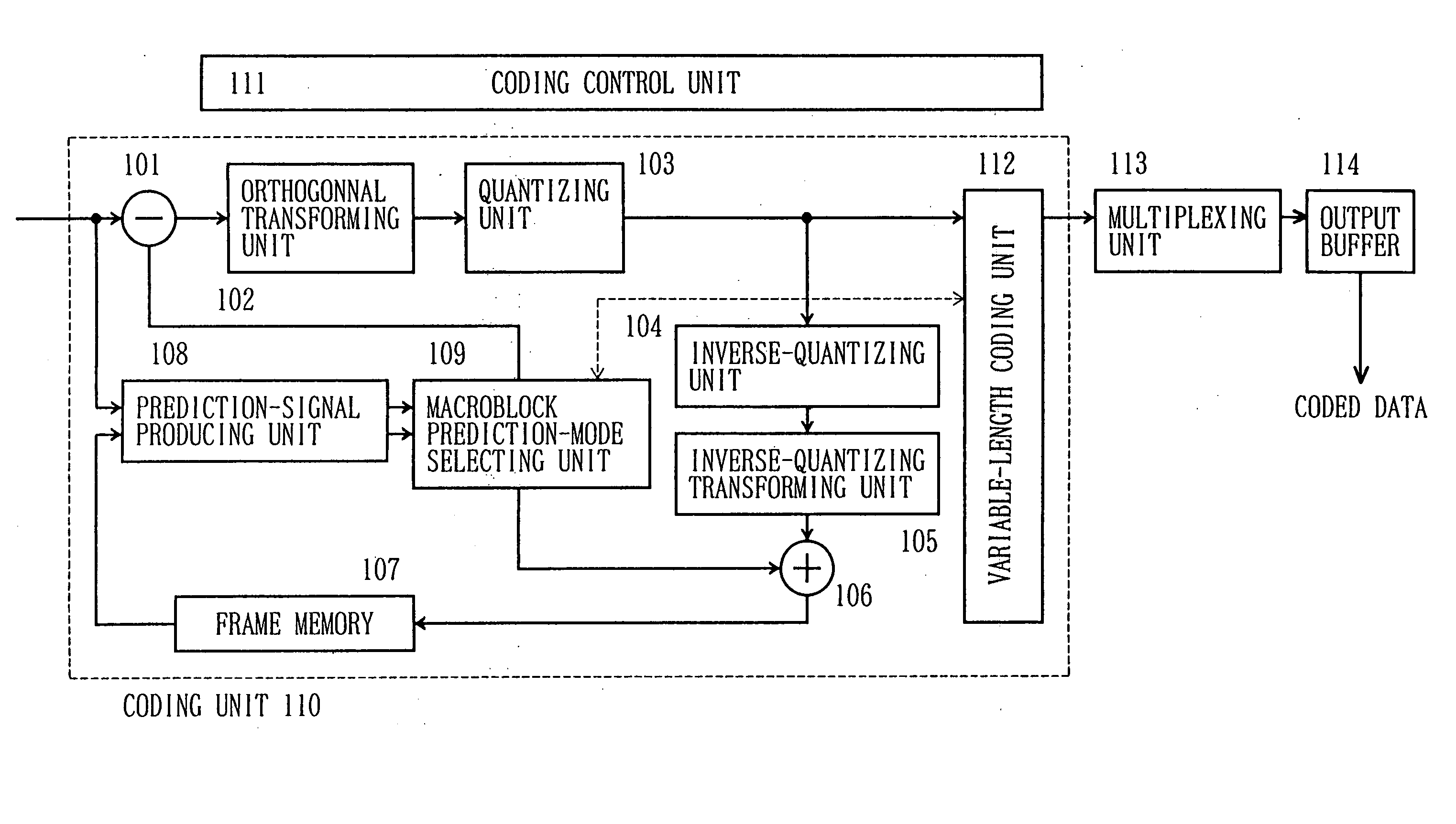
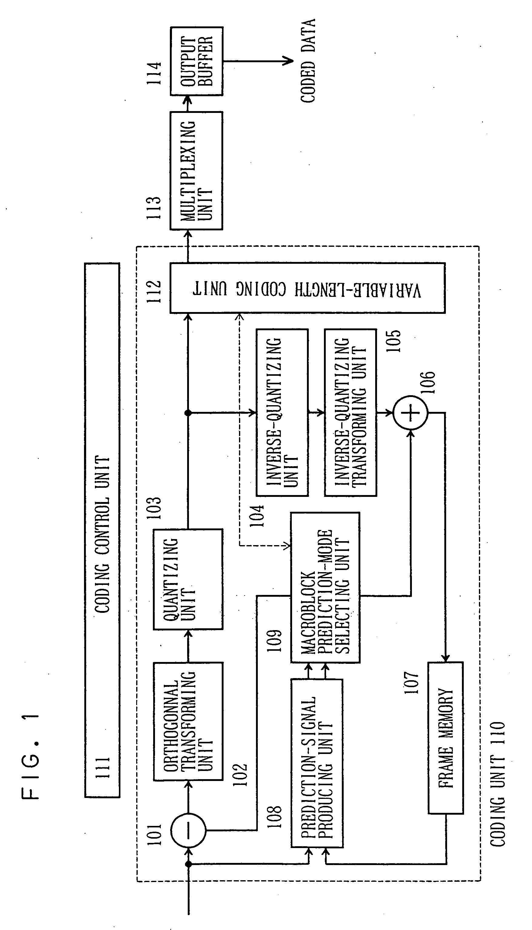
[0040]FIG. 1 is a block diagram for schematically showing an arrangement of a moving picture coding apparatus according to a first embodiment of the present invention.
[0041] (1) Arrangement of Moving Picture Coding Apparatus
[0042] In the moving picture coding apparatus of FIG. 1, a moving picture signal is inputted to a coding unit 110. A subtracter 101 of this coding unit 110 is connected via an orthogonal transforming unit (for example, discrete cosine transforming device) 102 and a quantizing unit 103 to a variable length coding unit 112. The orthogonal transforming unit 102 orthogonally transforms an input signal (moving picture signal). The quantizing unit 103 quantizes an orthogonal transforming coefficient (DCT coefficient). An output terminal of the quantizing unit 103 is connected via an inverse quantizing unit 104, an inverse orthogonal transforming unit 105, and an adder 106, which constitute a local decoding device, to a frame memory 107. An output terminal of the fram...
second embodiment
[0127] Next, a description is made of process operations in the case that an in-frame coding method is selected by the prediction control unit 201, according to a second embodiment of the present invention.
[0128] The second embodiment is featured as follows: At first stage, executed on first hand is a prediction mode having a prediction direction that is calculated from a plurality of pre-coded adjoining blocks. At next stage, rough-estimate coding costs are calculated by use of prediction modes that has been selected out, as to become less dense, from a plurality of possible prediction directions. Thus, a predominant direction is determined which corresponds to such a prediction direction whose rough-estimate coding cost becomes minimum. Then, rough-estimate coding costs are calculated with respect to prediction directions in vicinity of a direction that is judged to be the predominant direction; namely, with respect to prediction modes having inclinations or gradients of directio...
third embodiment
[0148] Next, a description is made of a third embodiment of the present invention as to a mode selecting operation of a 16×16 prediction.
[0149] In this third embodiment, a mode judging operation for a 4×4 pixel block or a small pixel block is executed in advance, so that mode information of the small pixel block is utilized in judging of a large pixel block.
[0150] (1) Arrangement of First Mode Judging Unit 106
[0151]FIG. 10 shows an arrangement of a first mode judging unit 1006 when a 16×16 prediction is selected. An arrangement of a second mode judging unit in this embodiment is same with that of FIG. 3; therefore, only the first mode judging unit 1006 is represented in the FIG. 10.
[0152] In the 16×16 prediction, in order to execute a process operation in a high speed, 4×4 prediction mode information 1001 is employed which is determined by the 4×4 prediction. A prediction mode dispersion calculating unit 1002 calculates dispersion of the above-described 4×4 prediction mode inform...
PUM
 Abstract
Description
Claims
Application Information