Cutting method and cutting apparatus for layered sheet, layered sheet, optical element and image display

a cutting apparatus and layered sheet technology, applied in the direction of polarising elements, manufacturing tools, instruments, etc., can solve the problems of affecting the quality of layered sheets, and film may have a large rip along the expansion direction, so as to achieve the effect of enhancing the precision of the dimension of the gained layered sheet, and reducing the risk of ripping

Inactive Publication Date: 2005-07-21
NITTO DENKO CORP
View PDF14 Cites 11 Cited by
  • Summary
  • Abstract
  • Description
  • Claims
  • Application Information

AI Technical Summary

Benefits of technology

[0023] As a result of this, the above described working effects can be appropriately gained. That is to say, cutting can be efficiently carried out without fail in a manner where the condition of the cross section of the layered sheet after the cutting is excellent and ripping does not easily occur along the expansion direction and in addition, precision in the dimensions of the gained layered sheet can be properly enhanced.

Problems solved by technology

In addition, in the case where an adhesive layer is included, some adhesive may protrude due to the pressure at the time of cutting.
It is necessary to remove such fragments that have appeared and such protrusions of the adhesive because they may cause deterioration in the quality during the subsequent processes.
However, the film may have a large rip along the expansion direction at the time of cutting according to the prior art disclosed in Japanese Unexamined Patent Publication No.
S61(1986)-136746, which becomes a problem due to poor appearance.
In addition, in recent years LCD panels tend to have narrow frames according to the specification, and the requirements of the precision in the dimensions of the polarizing plates to be mounted on the panels, and of the appearance of the end portions of the polarizing plates have become stricter and stricter.

Method used


Image

  • Cutting method and cutting apparatus for layered sheet, layered sheet, optical element and image display
  • Cutting method and cutting apparatus for layered sheet, layered sheet, optical element and image display
  • Cutting method and cutting apparatus for layered sheet, layered sheet, optical element and image display

Examples


examples

[0093] Next, examples which concretely show the configuration and the effects of the present invention are described. A polarizing plate that is mounted on a liquid crystal display where high levels of processing precision and finishing precision are required is utilized in order to evaluate each of the following items. In this polarizing plate, transparent protective layers are provided on both sides of a polarizing film, a film for increasing linear polarization separated brightness that utilizes multilayer interface reflection is provided on the surface of the transparent protective layer, on one side, via an adhesive layer, and in addition, a protective film for preventing scratches and stains is provided to the surface of this film for increasing brightness. On the other hand, an adhesive layer for making the polarizing plate adhere to a liquid crystal display is formed on the surface of the transparent protective layer, on the other side, and this surface is provided with a li...

examples 1 to 5

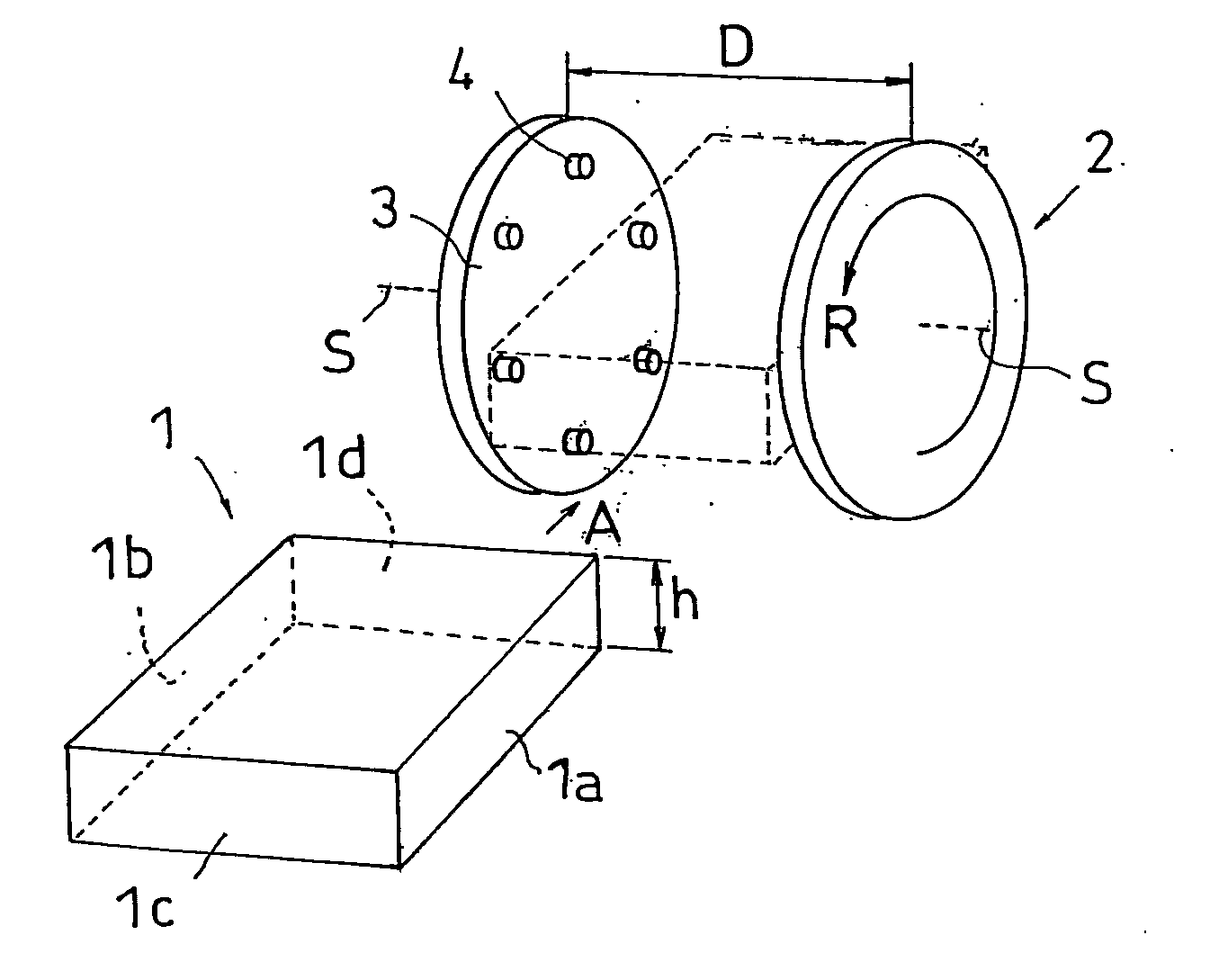
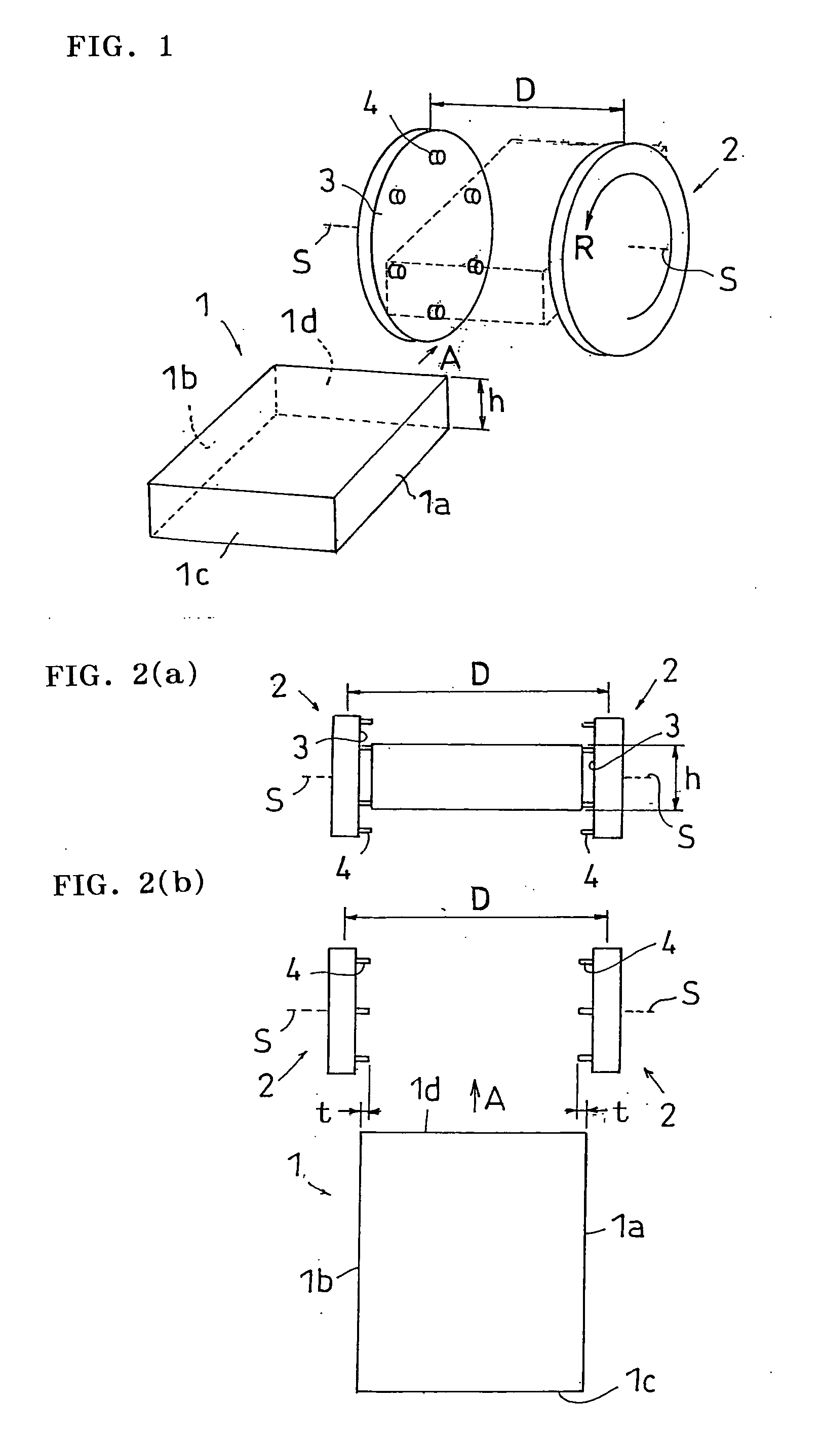
[0094] Thirty polarizing plates which are the same as the above described polarizing plate and which were cut to 310 mm×235 mm were layered in the direction of the thickness, and were cut to 305 mm×230 mm according to the above described embodiments. The rotation speed of the cutting members and the speed of movement of the support at the time of cutting are shown in Table 1, for each of Examples 1 to 5.


PUM

PropertyMeasurementUnit
distanceaaaaaaaaaa
distanceaaaaaaaaaa
total thicknessaaaaaaaaaa

Abstract

A cutting method and a cutting apparatus which allow a cross section of a layered sheet to be cut with high precision in a manner where the condition of this cross section is excellent and ripping does not easily occur along the expansion direction as well as a layered sheet and an optical member which have been cut according to this method, an optical element provided with this optical member and an image display on which this optical member or this optical element has been mounted are provided.

Description

BACKGROUND OF THE INVENTION [0001] 1. Field of the Invention [0002] The present invention relates to: a cutting method and a cutting apparatus for a layered sheet; a layered sheet that has been cut according to this method; an optical element provided with this layered sheet; and an image display on which this layered sheet or this optical element has been mounted, and is particularly useful in the case where a polarizing plate is used as a layered sheet. [0003] 2. Description of the Related Art [0004] Polarizing plates are widely used as components of liquid crystal display (hereinafter may be referred to by the abbreviation LCD) and the demand thereof has dramatically increased in recent years. In addition, the utilization of polarizing plates having a high added value provided with an optical compensation function, a brightness increasing function and the like, has also increased and a request for high quality displays tends to increase even more. A polarizing film made of a poly...

Claims


Application Information

Patent Timeline
Patent Type & Authority Applications(United States)
IPC IPC(8): G02F1/13B23C1/00B23C3/12B23D1/00B26D1/29G02B5/30
CPCB26D1/29Y10T409/307784Y10T409/50246Y10T409/50082G02F1/13
Inventor HIGASHIO, KAZUHIROMOTOMURA, HIRONORIKANATANI, MINORU
Owner NITTO DENKO CORP
Why Eureka
Try Eureka