Supercharge Your Innovation With Domain-Expert AI Agents!

Manufacturing method of shallow trench isolation structure

a manufacturing method and technology of shallow trenches, applied in the direction of semiconductor/solid-state device manufacturing, basic electric elements, electric devices, etc., can solve the problems of reducing the integration of devices and circuits drastically, and the foregoing methods cannot meet the requirements of the process

Inactive Publication Date: 2005-07-21
UNITED MICROELECTRONICS CORP
View PDF7 Cites 11 Cited by
  • Summary
  • Abstract
  • Description
  • Claims
  • Application Information

AI Technical Summary

Benefits of technology

[0010] Accordingly, one of the purpose of the present invention is to provide a manufacturing method of shallow trench isolation (STI) structure, to preclude the generation of the divot near the corner of the trench during the process.
[0014] Accordingly, since in the manufacturing method of shallow trench isolation (STI) structure of the invention, the bias power of the second stage process is larger than that of the first stage process, and / or the deposition to etching ratio of the second stage process is less than that of the first stage process, the isolation material deposited by the second stage process is denser. Moreover, since the isolation layer that fills the trench is denser, the divot generated around the corner of the trench during the removing of the mask layer and the pad oxide layer is mitigated, or eliminated.

Problems solved by technology

However, the disadvantages of the LOCOS method includes, at least some issues resulted from the stress and the generation of the bird's beak region around the isolation structure.
The generation of the bird's beak region will reduce the integration of the devices and circuits drastically.
However, when the integration of the device is getting higher, the size of the device is minimized and the specification of characteristic of the device is tightened, the foregoing methods can not meet the requirement of the process.

Method used


Image

  • Manufacturing method of shallow trench isolation structure
  • Manufacturing method of shallow trench isolation structure
  • Manufacturing method of shallow trench isolation structure

Examples


Embodiment Construction

[0021] The present invention now will be described more fully hereinafter with reference to the accompanying drawings, in which preferred embodiments of the invention are shown. This invention may, however, be embodied in many different forms and should not be construed as limited to the embodiments set forth herein; rather, these embodiments are provided so that this disclosure will be thorough and complete, and will fully convey the scope of the invention to those skilled in the art. Like numbers refer to like elements throughout.

[0022]FIG. 2A to FIG. 2F are cross-sectional views schematically illustrating a process flow of a shallow trench isolation (STI) structure according to a preferred embodiment of the invention.

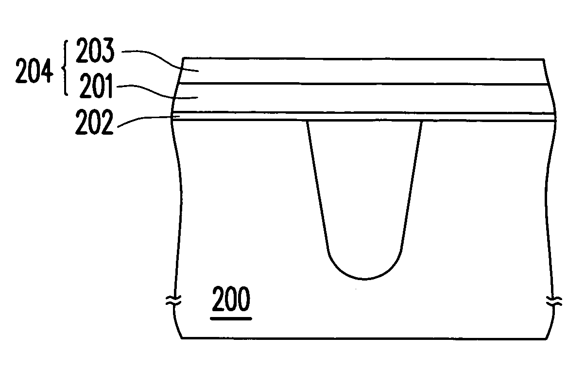
[0023] Referring to FIG. 2A, the manufacturing method of shallow trench isolation (STI) structure of the invention includes, for example but not limited to, providing a substrate 200. A pad oxide layer 202 and a mask layer 204 are formed on the substrate 200 sequen...


PUM


Abstract

A manufacturing method of shallow trench isolation (STI) structure is described. A substrate is provided, wherein a patterned pad oxide layer and a mask layer are formed on the substrate, and at least a trench is formed in the substrate, wherein the trench is formed by exposing a portion of the pad oxide layer and the mask layer. Then, a liner layer on a surface of the trench is formed. A high density plasma chemical vapor deposition (HDP-CVD) process is performed to form an isolation layer on the substrate and over the trench, wherein the trench is at least filled with the isolation layer. The HDP-CVD process includes a first stage process and a second stage process. The bias power of the second stage process is larger than the bias power of the first stage process. Thereafter, the isolation layer over the trench, the mask layer and the pad oxide layer are removed sequentially.

Description

BACKGROUND OF THE INVENTION [0001] 1. Field of the Invention [0002] The present invention generally related to a semiconductor process. More particularly, the present invention relates to a manufacturing method of shallow trench isolation (STI) structure. [0003] 2. Related Art of the Invention [0004] In recent years, when the level of integration of the semiconductor circuits and device is getting higher, the isolation between the circuits and the device becomes more important. The isolation layer is provided in the manufacturing process to prevent from the short between the neighboring devices and circuits. The conventionally manufacturing process of the isolation layer includes a localized oxidation isolation (LOCOS) method. The advantage of the LOCOS method is that the cost is low and the performance of the isolation structure between the devices and circuits is good. However, the disadvantages of the LOCOS method includes, at least some issues resulted from the stress and the ge...

Claims


Application Information

Patent Timeline
Patent Type & Authority Applications(United States)
IPC IPC(8): H01L21/311H01L21/316H01L21/762
CPCH01L21/02164H01L21/02274H01L21/76232H01L21/31612H01L21/02304
Inventor CHEN, NENG-KUOTSAI, TENG-CHUNCHU, HSIU-CHUANHUANG, CHIH-AN
Owner UNITED MICROELECTRONICS CORP
Features
  • R&D
  • Intellectual Property
  • Life Sciences
  • Materials
  • Tech Scout
  • Unparalleled Data Quality
  • Higher Quality Content
  • 60% Fewer Hallucinations
Learn More