Flexible couplings

a flexible coupling technology, applied in the field of assemblies, can solve the problems of limiting the functionality of the coupling, unable to provide dampening, and essentially no flexibility, and achieve the effects of low manufacturing cost, good dampening qualities, and minimal backlash

Inactive Publication Date: 2005-07-21
WEBER AIRCRAFT INC
View PDF9 Cites 4 Cited by
  • Summary
  • Abstract
  • Description
  • Claims
  • Application Information

AI Technical Summary

Benefits of technology

[0015] The present invention provides alternatives to these and other existing couplings. Designed to accommodate substantial angular misalignment, medium speeds, and high torques, the couplings of the invention also permit simultaneous axial and parallel shaft misalignments. The couplings additionally are reliable, relatively inexpensive to manufacture, and do not require maintenance of close tolerances. They further may be small in size yet scalable if necessary to meet demand for larger sizes. Other beneficial characteristics of the couplings include maintenance of rotational motion transfer notwithstanding failures of portions of the couplings, relatively few parts, minimal backlash, good dampening qualities, no need for lubrication, and ability to withstand high shock force loads without failure.
[0019] Various embodiments of the invention allow the center member to be made of either elastomeric or rigid material. Using elastomeric material to form the center member likely would improve torsional dampening characteristics of the couplings while increasing backlash. Employing rigid plastic or other material for the center member should result in decreased backlash but decreased dampening as well.

Problems solved by technology

Numerous issues are presented in designing a suitable coupling, with variables such as torque, speed, misalignment, dampening, backlash, cost, size, reliability, ease of maintenance, and ease of manufacture needing to be considered.
At least some couplings are rigid, providing essentially no flexibility.
Regardless of fastening mechanism, though, these couplings tolerate essentially no shaft misalignment and cannot provide any dampening.
By contrast, possible failures of the protruding members under load or shock limit the functionality of these couplings.
Helical beam couplings further likely will not support high torque levels and are relatively expensive.
Failures of the disc may occur, however, and no axial (and little angular) misalignment of shafts is permitted.
However, rather than utilizing protruding members, pinhole-disc couplings employ dowel pins on half of the face of the coupling hub.
Again, though the (usually plastic) discs, or the dowel pins, may fail in use; additionally, no axial shaft misalignment is permitted and only limited dampening is available.
They permit neither axial shaft misalignment nor dampening to occur, however, and because of their shape are relatively expensive to manufacture.
However, they are relatively expensive to manufacture, require substantial maintenance, tend to vibrate at high speeds, and need lubrication on many metal sleeve designs.
These couplings fail to permit dampening and are relatively expensive to manufacture; as well, because the elastomeric material is large, they require substantial space for operation.
Similar to the double-loop couplings, these tire couplings require significant space in which to operate and are expensive to produce.
They further are heavier than most other couplings and do not support large torques.
Shear couplings also do not permit any axial misalignment of shafts and allow only low angular and parallel misalignments.
Possibility of failure of the elastomeric elements remains an issue for these couplings, are does their limited ability to tolerate misaligned shafts.
Lubrication is required for the couplings, however, and misalignment tolerances are small.
Failure of the chain, further, will result in the coupling being unable to transfer rotational motion.
Among disadvantages of the “Big Boy” coupling are that it appears to require close tolerances for operation and is expensive to manufacture.
It is large in size, however, and both expensive and designed for heavy industrial use.

Method used


Image

  • Flexible couplings
  • Flexible couplings
  • Flexible couplings

Examples


Embodiment Construction

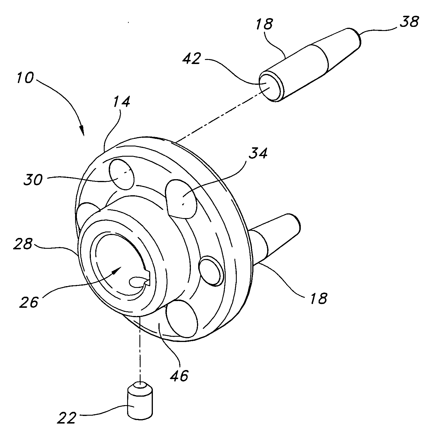
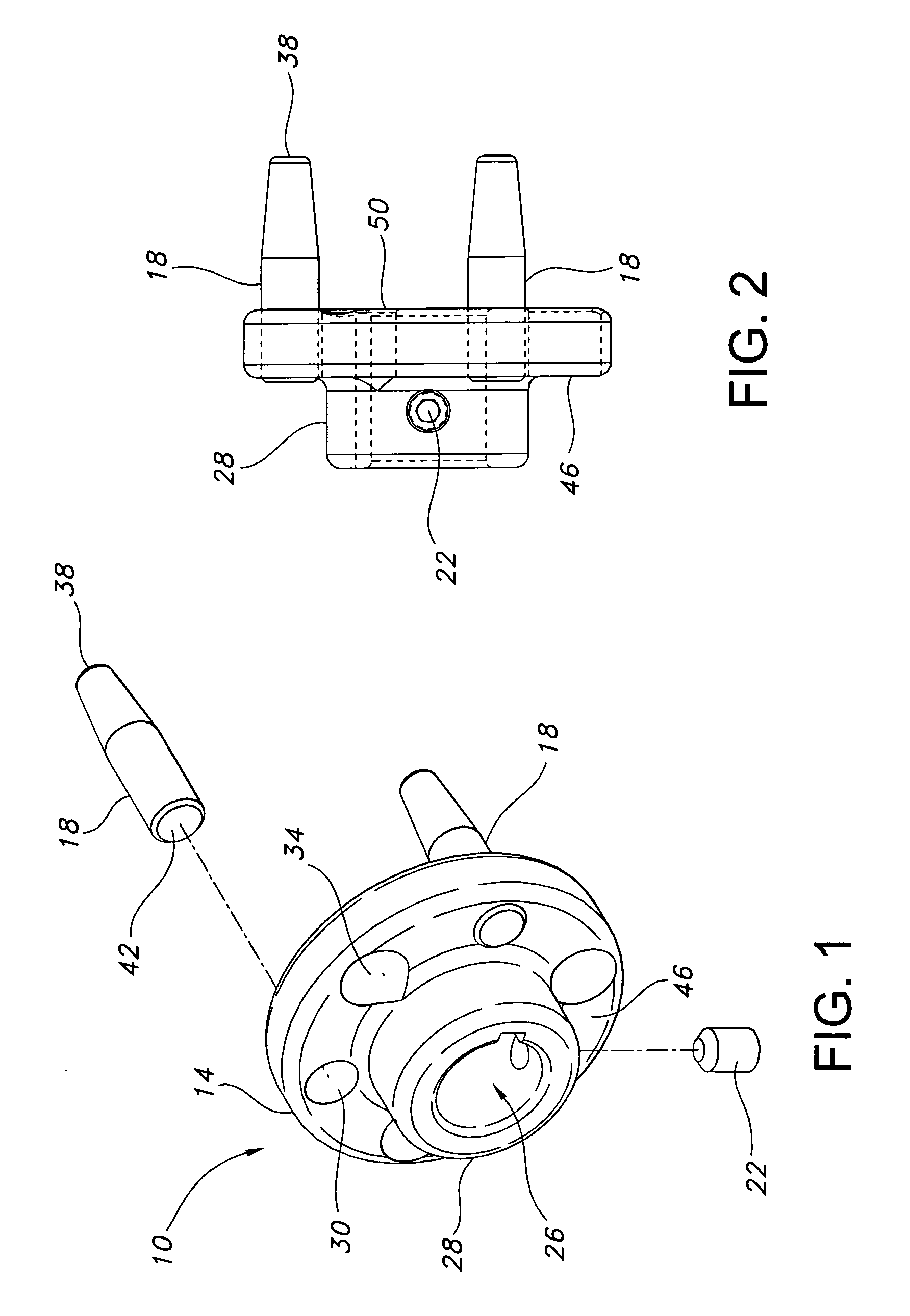
[0033] Illustrated in FIGS. 1-2 is hub assembly 10. Assembly 10 comprises hub 14 and one or more pins 18. Also included as part of assembly 10 may be fastener 22, which is shown in FIGS. 1-2 as comprising a set screw. However, those skilled in the appropriate art understand that devices other than or in addition to a set screw may be utilized as fastener 22.

[0034] Depicted in hub 18 is bore 26, defined by collar 28 and designed to receive, in use, a rotating shaft. After such a shaft is received in bore 26, fastener 22 may be tightened to fix the position of the shaft relative to hub 18. One or more openings 30 in hub 18 receive pins 18. Pins 18 typically are pressed into openings 30 and maintained therein with a friction fit. They need not, however, be so pressed, but instead may be connected to hub 14 in any suitable way or integrally formed therewith.

[0035] Also illustrated in hub 14 are one or more clearance holes 34. Shown as interspersed radially with openings 30, clearance ...


PUM

PropertyMeasurementUnit
rotationaaaaaaaaaa
elastomericaaaaaaaaaa
flexibleaaaaaaaaaa

Abstract

Addressed are couplings for transferring rotational motion from one shaft to another. The couplings may include flexible components and may be designed to accommodate angular, axial, and parallel misalignments. Included as components of the couplings may be hub portions, each having dowel pins and clearance holes, and a center member positioned intermediate the hub portions.

Description

FIELD OF THE INVENTION [0001] This invention relates to assemblies for transferring motion from one shaft to another and more specifically to couplings that are flexible or may, if desired, contain flexible components. BACKGROUND OF THE INVENTION [0002] Couplings conventionally are used to transfer motion from one machine shaft to another. Numerous issues are presented in designing a suitable coupling, with variables such as torque, speed, misalignment, dampening, backlash, cost, size, reliability, ease of maintenance, and ease of manufacture needing to be considered. Consequently, many couplings either are designed for particular purposes or function optimally only in certain circumstances. [0003] At least some couplings are rigid, providing essentially no flexibility. Often cylindrical in shape, these couplings include openings on each end of the cylinder to receive shafts. Typically set screws are used to lock the received shafts into position, although some versions of rigid cou...

Claims


Application Information

Patent Timeline
Patent Type & Authority Applications(United States)
IPC IPC(8): F16D3/48F16D3/78
CPCF16D3/48Y10T29/4984Y10T29/49826F16D3/78
Inventor GILBERT, KLAY ETHAN
Owner WEBER AIRCRAFT INC
Why Eureka
Try Eureka