Optical system for stereoscopic rigid endoscope

Inactive Publication Date: 2005-07-21
HOYA CORP
View PDF13 Cites 80 Cited by
  • Summary
  • Abstract
  • Description
  • Claims
  • Application Information

AI Technical Summary

Benefits of technology

[0010] The present invention is advantageous in that an improved stereoscopic rigid endoscope is provided which has a single relaying optical system in the insertion unit, and a pair o

Problems solved by technology

Therefore, it is difficult to downsize the tip end radius of the insertion unit.
Therefore, the incident pupil diameter is very small, and the stereoscopic rigid endoscope according to the second embodiment may not have a sufficient base length.
Therefore, i

Method used


Image

  • Optical system for stereoscopic rigid endoscope
  • Optical system for stereoscopic rigid endoscope
  • Optical system for stereoscopic rigid endoscope

Examples


first embodiment

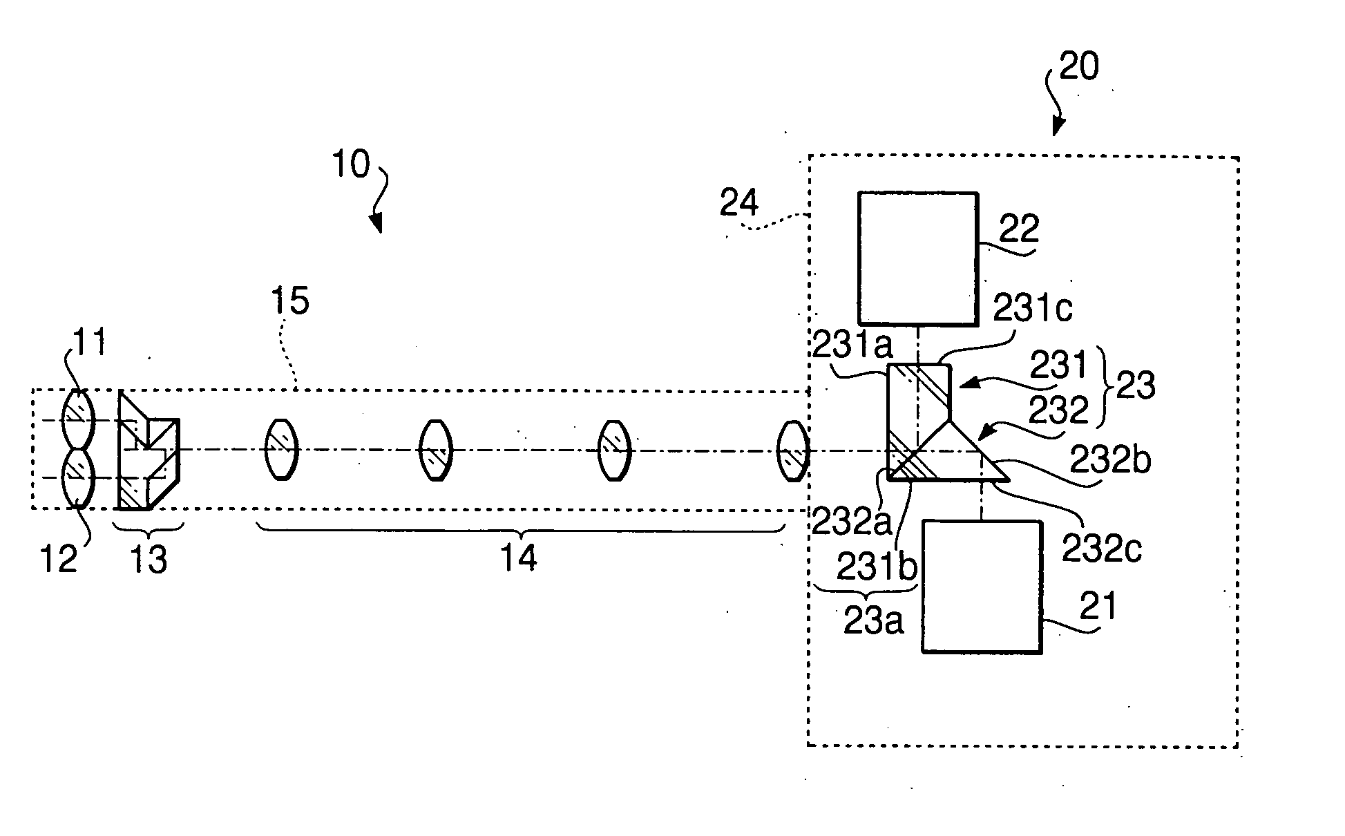
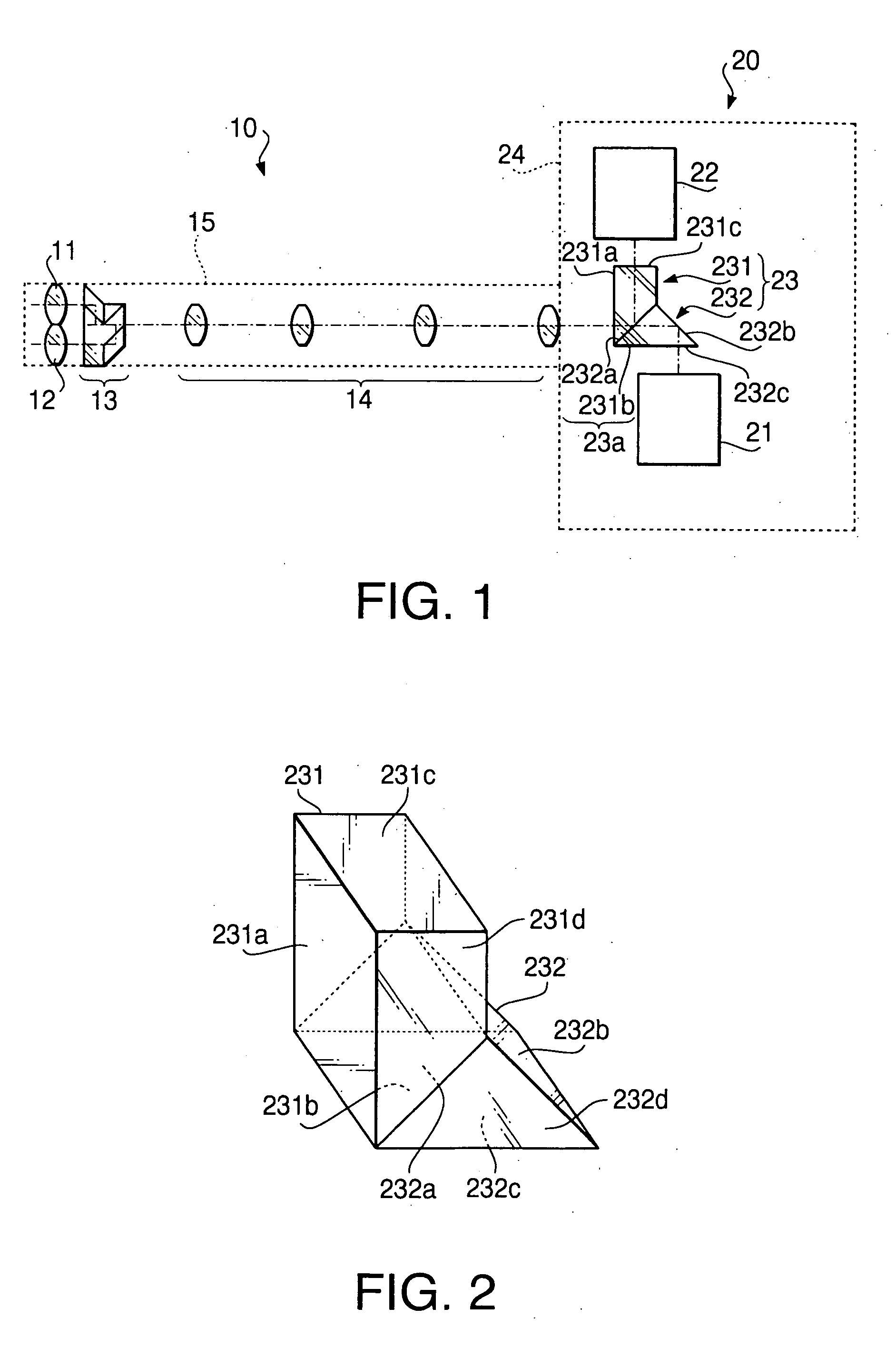
[0030]FIG. 1 schematically shows a configuration of a stereoscopic rigid endoscope according to a first embodiment of the invention. The stereoscopic rigid endoscope includes an insertion unit 10 and an image capturing unit 20.

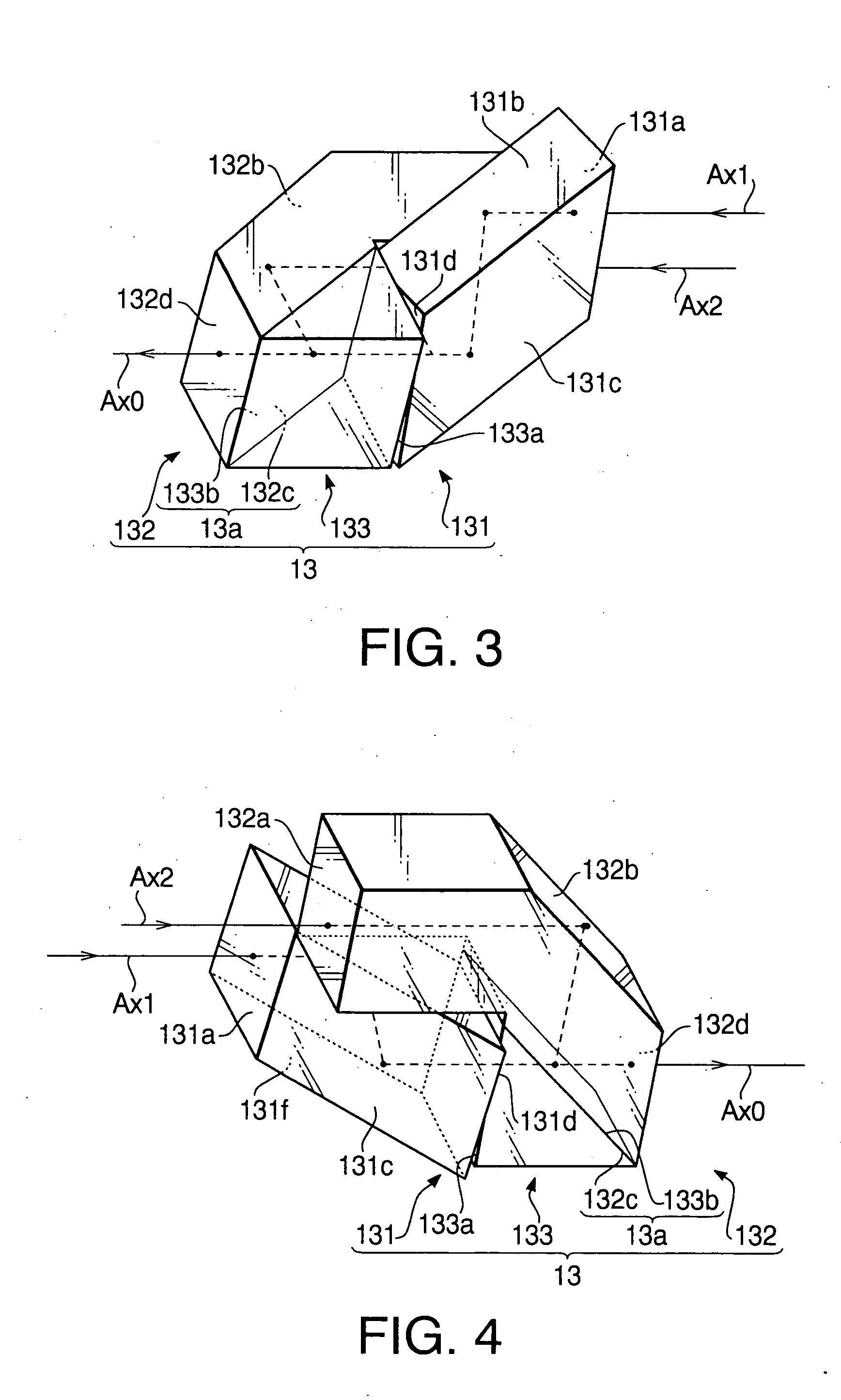
[0031] The insertion unit 10 includes, as its principal compositions, a first objective optical system 11, a second objective optical system 12, an optical path combining element 13, a relaying optical system 14 and a sheath 15. The sheath 15 is an elongated tubular member which can be inserted inside an objective such as inside a human body, machine and fragments of broken material. The sheath 15 fixedly holds therein a lens barrel which contains the first and second objective optical systems 11 and 12 and the relaying optical system 14, and the optical path combining element 13.

[0032] The first objective optical system 11 and the second objective optical system 12 are optical systems for forming an object facing the tip of the insertion unit 10. The first ...

second embodiment

[0080]FIG. 9 schematically shows a configuration of a stereoscopic rigid endoscope according to a second embodiment of the invention. As shown in FIG. 9, when compared with FIG. 1, the endoscope is provided with a liquid crystal (LC) shutter 25 instead of the optical path splitting element 23, and only a single imaging device 26 is provided instead of the first and second imaging devices 21 and 22 of the first embodiment. The other configuration of the second embodiment similar to that of the first embodiment, only different portions with respect to the first embodiment will be described hereinafter.

[0081] The LC shutter 25 alternately transmits a polarized light component having a predetermined polarization direction and another polarized light component having a polarization direction perpendicular to the other at a predetermined interval (e.g., one-sixtieth seconds). The LC shutter 25 is fixed inside the casing 24 of the image capturing unit 20. The LC shutter 25 is arranged suc...


PUM


Abstract

An optical system for stereoscopic rigid endoscope is provided with first and second objective optical systems arranged to have a predetermined clearance therebetween and an optical path combining system that polarizes light passed through the first and second objective optical systems in directions perpendicular to each other. The optical path combining system parallelly shifts the optical axes of the first and second objective optical systems so that they coincide with each other. The shifting directions of the optical axes form an angle less than 90 degrees. A relaying optical system is provided inside the insertion unit of the endoscope. An optical axis of the relaying optical system is coaxial with the combined optical axes. An optical image separating system separates the light passed through the relaying optical system into first and second components that passed through the first and second objective optical systems and polarized by the optical path combining system, respectively.

Description

BACKGROUND OF THE INVENTION [0001] The present invention relates to an optical system incorporated in a stereoscopic rigid endoscope. [0002] Conventionally, a rigid endoscope has been widely used to observe inside of human bodies, machines, debris and the like. Conventional rigid endoscope has been provided with a single optical system and observation is performed with one eye. With such a conventional rigid endoscope, only a two-dimensional view can be observed. In order to carry out various treatment inside the object precisely, a three-dimensional view of the object is desired. For this purpose, recently, a stereoscopic rigid endoscope has been developed and used. An example of such a stereoscopic rigid endoscope is disclosed in Japanese Patent Provisional Publication No. 05-341207. [0003] The stereoscopic rigid endoscope system described as a first embodiment in the publication is provided with a pair of object optical systems each including a polarization plate and a pair of ey...

Claims


Application Information

Patent Timeline
IPC IPC(8): A61B1/00G02B23/26
CPCA61B1/00193
Inventor KANAI, MORIYASU
Owner HOYA CORP
Why Eureka
Try Eureka