
Identification document and related methods

a technology of identification documents and identification documents, applied in the field of identification documents, can solve the problems of difficult detection, difficulty in confirming by inspection that the individual depicted in the photograph of the identification card is the individual depicted in the photograph, and the damage of the card is not visible, so as to achieve enhanced security and certainty in the use.

Inactive Publication Date: 2005-07-21
DIGIMARC CORP
View PDF99 Cites 253 Cited by
  • Summary
  • Abstract
  • Description
  • Claims
  • Application Information

AI Technical Summary

Benefits of technology

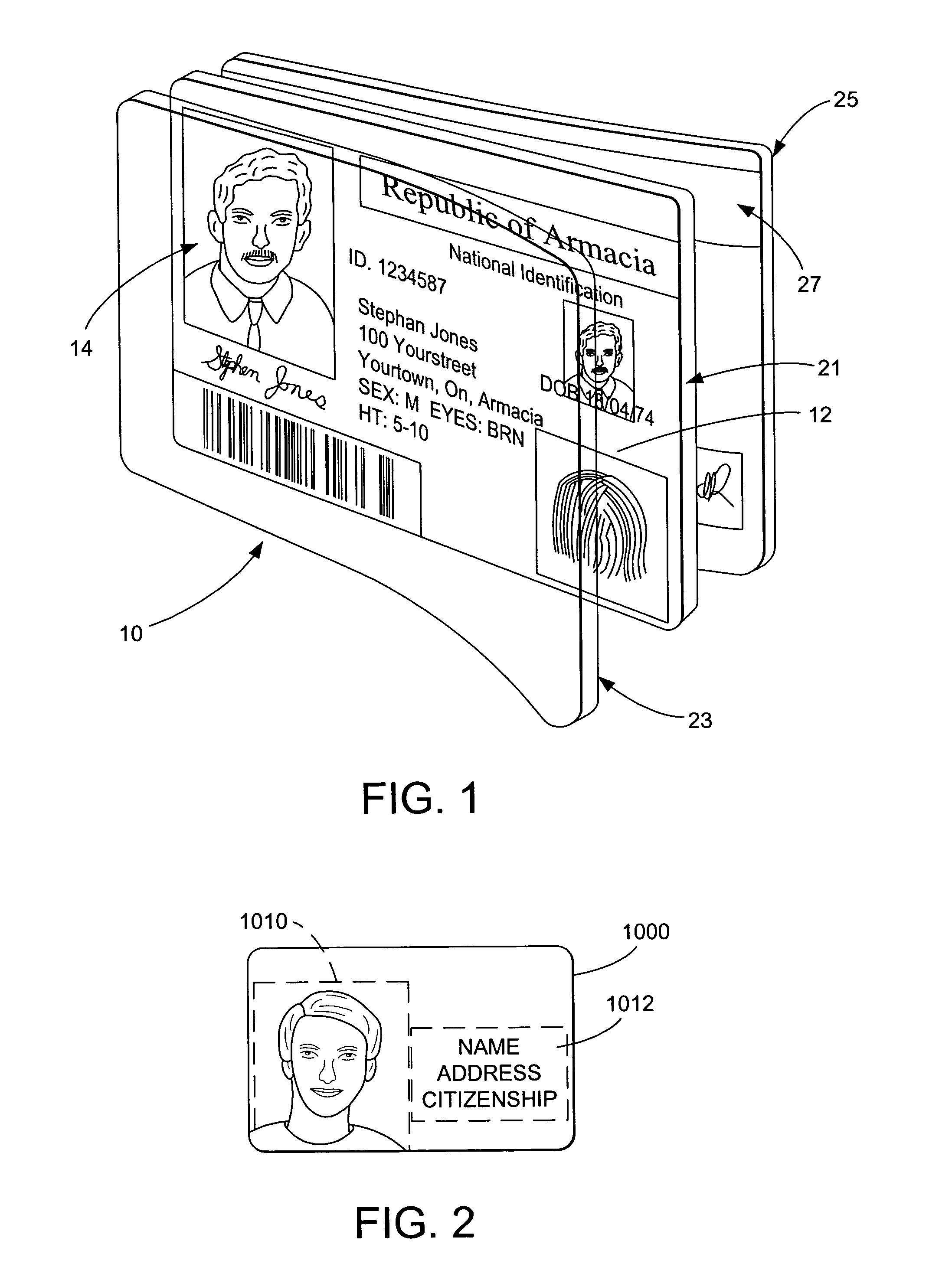
[0007] The printed substrate 21 is usually laminated. The laminate typically includes a plastic, polyester or polycarbonate-based top sheet 23 and bottom sheet 25 that respectively overlay the top and bottom of the substrate 21. Heat and / or adhesives and pressure are used to bond the laminate sheets 23 and 25 with the substrate 21. Or a laminate can include a pouch into which the substrate 21 slips. Again, heat and / or adhesives and pressure are used to bond the substrate 21 with a pouch laminate. The laminates provide a protective covering for the printed substrate and provide a level of protection against unauthorized tampering. (For example, a laminate would have to be removed to alter the printed information and then subsequently replaced after the alteration.). A laminate layer 23 or 25 may optionally carry information like a card bearer's signature or security features.
[0018] The photo ID document includes a photograph 1010 that is attached to the document 1000. Printed, human-readable information 1012 is incorporated in the document 1000, adjacent to the photograph 1010. Machine-readable information, such as that known as “bar code” may also be included adjacent to the photograph. Generally, the photo ID document is constructed so that tampering with the document (for example, swapping the original photograph with another) should cause noticeable damage to the card. Nevertheless, skilled forgers are able to either alter existing documents or manufacture fraudulent photo ID documents in a manner that is extremely difficult to detect. Security associated with the use of photo ID documents is enhanced by supplementing the photographic image with encoded information (which information may or may not be visually perceptible), thereby facilitating the correlation of the photographic image with other information concerning the person, such as the printed information 1012 appearing on the document 1000.
[0024] One aspect of this invention provides enhanced security and certainty in the use of photo identification documents.

Problems solved by technology

Generally, the photo ID document is constructed so that tampering with the document (for example, swapping the original photograph with another) should cause noticeable damage to the card.
Nevertheless, skilled forgers are able to either alter existing documents or manufacture fraudulent photo ID documents in a manner that is extremely difficult to detect.
Fraudulent use of identification documents may occur where, for example, an otherwise legitimate identification document is modified such that the original photograph is swapped with that of another person, thereby enabling the other person to masquerade, at least temporarily, under the guise of the original identification document holder.
Even in the absence of photo swapping or alteration, it is oftentimes difficult to confirm by inspection that the individual depicted in the photograph of the identification card is indeed the bearer of the card.

Method used


Image

  • Identification document and related methods
  • Identification document and related methods
  • Identification document and related methods

Examples


first embodiment

[0045] Forensics and Proof of Compliance

[0046] As discussed above with respect to our '886 patent, a photo-ID can be enhanced through embedding data therein. Data can be embedded in, e.g., a graphic or background of the photo-ID. More preferable, however, is to embed the data in a photograph image. The watermark is preferably robust, in that it survives scanning and printing. In some implementations of this embodiment, the watermark is repeated or redundantly embedded throughout an image or document.

[0047] Although sometimes redundantly embedded across an entire document surface, a watermark can be embedded in a particular region of the document if desired (e.g., only in a photograph or a graphic). In an area-based embedding implementation, we can use a mask to identify areas for embedding (or areas that will not receive embedding). The watermark is embedded in identified areas (or is embedded to avoid areas). The watermark can also include a so-called orientation component. An ori...

second embodiment

[0052] Multiple Watermarks

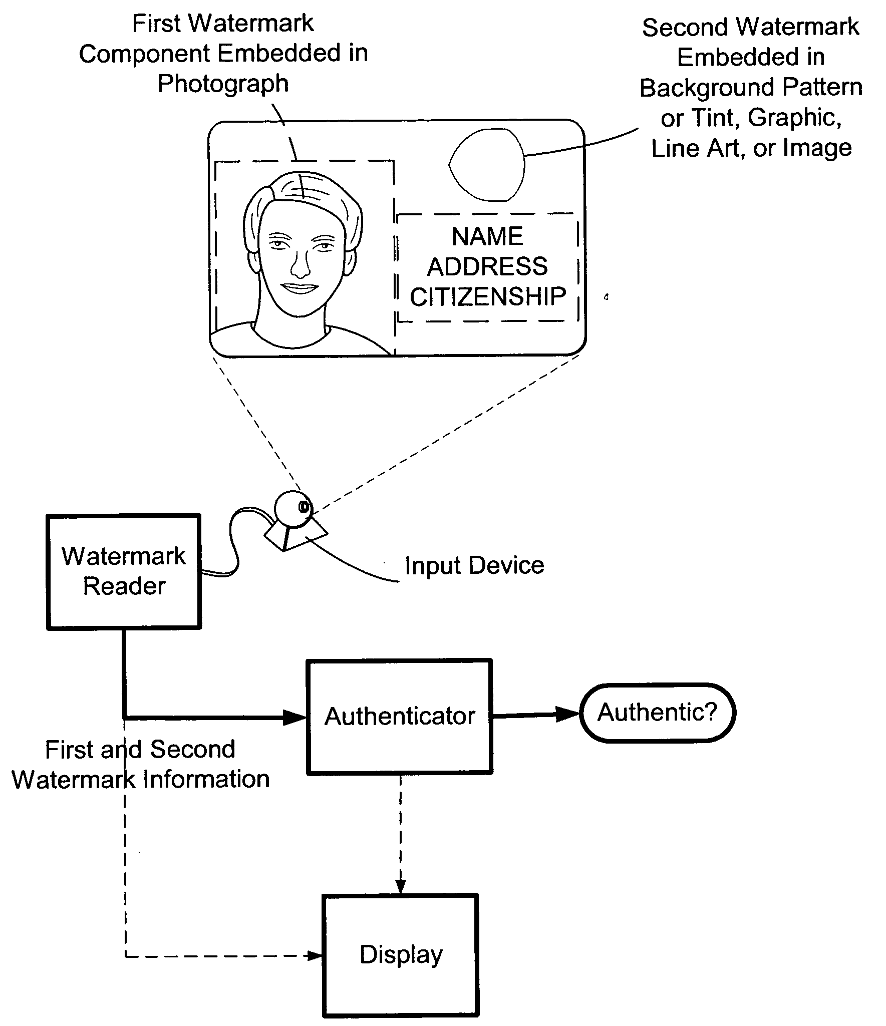
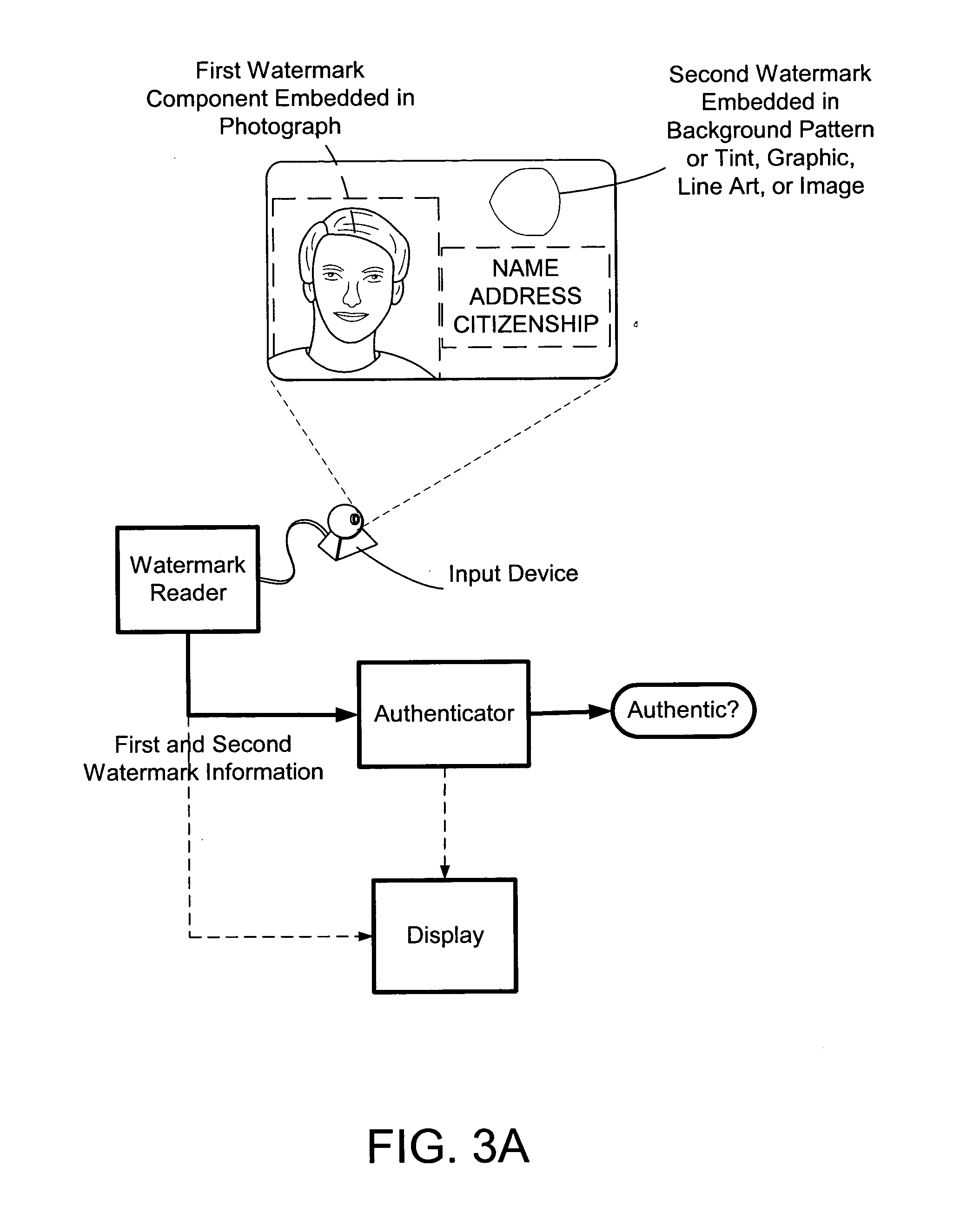
[0053] Additional security is added to an identification document by providing first and second digital watermarks on the identification document. For example, a first digital watermark is embedded in first region of the identification document like in a photograph, artwork, graphic, seal, or image (e.g., ghost image). And a second digital watermark is provided in a second region of the identification card. For example, the second digital watermark is embedded in a background pattern or tint, line-art (see, e.g., assignee's U.S. Pat. No. 6,449,377) or in text, artwork, seal, images or graphics carried by the identification document. The first and second watermarks also may include a so-called orientation component. An orientation component is helpful to resolve image distortion such as rotation, scale and translation. (We note that the second watermark can be embedded using the same or different embedding protocol as the first watermark.). Although not nece...

third embodiment

[0085] Fragile Watermarks

[0086] A fragile or semi-fragile watermark is provided to any of the first and second embodiments as either a watermark replacement or to augment the above implementations. For example, in the second embodiment, a fragile watermark may be used as either the first or second watermark or as a third watermark component. In some implementations we preferably use our out-of-phase embedding techniques, e.g., as disclosed in PCT / US02 / 20832 (published in English as WO 03 / 005291), to embed a fragile watermark. It will be appreciated that a fragile watermark is designed to be lost or to predictably degrade upon certain types of signal processing. A semi-fragile watermark is designed to withstand normal signal processing, but is destroyed or predictably degrades upon malicious attacks.

[0087] The addition of a fragile or semi-fragile watermark adds protection against anticipated fraud scenarios by providing alerts when copies are made. Alteration in conjunction with ca...


PUM


Abstract

The present invention provides methods and systems for authenticating identification documents. We also teach an identification document including two or more digital watermarks. The watermarks correspond with each other or with indicia carried by the identification document. The correspondence can be verified to determine authenticity. We also provide digital watermark detection methods and systems to identify the different watermarks through embedded orientation components. We then focus watermark message-decoding efforts on areas identified as likely including watermark orientation components. In one implementation we provide a watermark detection trigger to identify so-called legacy documents. The trigger may indicate the presence or expected absence of a digital watermark. In other implementations we provide a versatile document authenticator to toggle between watermarking and non-watermarking authentication processes depending on a detection trigger.

Description

RELATED APPLICATION DATA [0001] The present application claims the benefit of U.S. Provisional Patent Application Nos. 60 / 418,762, filed Oct. 15, 2002, 60 / 421,254, filed Oct. 25, 2002, 60 / 494,709, filed Aug. 12, 2003, 60 / 495,236, filed Aug. 13, 2003 and 60 / 495,373, filed Aug. 14, 2003. Each of these patent documents is herein incorporated by reference. [0002] This application is also related to assignee's U.S. patent application Ser. No. 09 / 945,244, filed Aug. 31, 2001 (published as 20020057823 A1), Ser. No. 09 / 503,881 (now U.S. Pat. No. 6,614,914), Ser. No. 09 / 452,023 (now U.S. Pat. No. 6,408,082), Ser. No. 10 / 366,541, filed Feb. 12, 2003 (published as US 2003-0179903 A1), Ser. No. 09 / 433,104, filed Nov. 3, 1999 (allowed), Ser. No. 10 / 032,282, filed Dec. 20, 2001 (published as US 2002-0114491 A1), and Ser. No. 09 / 498,223, filed Feb. 3, 2000 (now U.S. Pat. No. 6,574,350), and U.S. Pat. No. 6,389,151. The Ser. No. 10 / 366,541 application is a grandchild of assignee's U.S. Pat. No. 5,8...

Claims


Application Information

Patent Timeline
Patent Type & Authority Applications(United States)
IPC IPC(8): B42D15/10G06T1/00G07D7/12G07F7/08G07F7/12H04N1/32
CPCB42D15/10H04N2201/3205G06Q20/347G06Q20/401G06T1/0028G06T1/0071G06T2201/0051G07D7/002G07F7/08G07F7/086G07F7/12H04K1/00H04N1/32144H04N1/32304H04N1/32352B42D2035/34H04N1/32288H04N2201/3233H04N2201/3235H04N2201/327G09C5/00H04L9/3231H04L2209/56H04L2209/608H04L2209/805B42D25/00B42D25/309G07D7/0034B42D25/47B42D25/23B42D25/333B42D25/20
Inventor BRUNDAGE, TRENT J.SHER-JAN, MAHMOODWEAVER, MATTHEW M.HANNIGAN, BRETT T.BRADLEY, BRETT A.STACH, JOHNPERRY, BURT W.DURST, ROBERT T. JR.RHOADS, GEOFFREY B.
Owner DIGIMARC CORP
Learn More