Air-ventilating shoe sole

Inactive Publication Date: 2005-07-28
LIOU TIAN AN
10 Cites 11 Cited by

AI-Extracted Technical Summary

Problems solved by technology

Closed shoes of the prior art generally have the problem of air ventilation.
Therefore, vent holes exposed on the outer surface of the shoe are inevitable, which constantly caused a consumer's doubt...

Method used

[0022] The air-ventilating structure of the shoe sole 1 is integrally formed with the shoe sole 1, which not only lowers the production cost but also prevents affecting the outlook and the comfort of the shoe the shoe sole I attached to.
[0025] Referring to FIGS. 7 and 8, the fourth preferred embodiment of the present invention has a pair of flanges 1′0 respectively extending from two lateral sides of the shoe sole 1′, corresponding to the arch portion of the feet. Each of the flanges 1′0 is provided with two the air chambers 1′01, 1′02. The air chambers 1′01, 1′02 are respectively provided with vent holes 10′3, 10′4, which go through the top portions of flanges 1′0. The bottom ends of the air chambers 1′01, 1′02 are connected two an Ω-shaped or an λ-shaped air passages 1′8 or 1′9, as shown respectively in FIGS. 7 and 8. Thereby, the cool air outside can flows through the vent holes 10′3, 10′4 into the air chambers 1′01, 1′02 and then into air passages 1′8 or 1′9 for mixing with ...

Benefits of technology

[0004] Accordingly, the primary objective of the present invention is to provide ...

Abstract

An air-ventilating shoe sole has a plurality of connected passages on the top surface thereof for ventilating air. The air passages are connected to a plurality of vertically elongated air chambers on a flange extending from the rear side of the shoe sole, thereby forming a plurality of L-shaped air-ventilating structures. The upper ends of the air chambers are respectively provided with vent holes for exchanging cool air outside with the warm and humid air inside. The positions of the vent holes effectively prevent inward permeation of water. The air-ventilating structure is integrally formed within the shoe sole that it does not influence the outlook and the comfort of the shoe.

Application Domain

Footwear

Technology Topic

Cold airFlange +1

Image

  • Air-ventilating shoe sole
  • Air-ventilating shoe sole
  • Air-ventilating shoe sole

Examples

  • Experimental program(1)

Example

[0018] The various objects and advantages of the present invention will be more readily understood from the following detailed description when read in conjunction with the appended drawings.
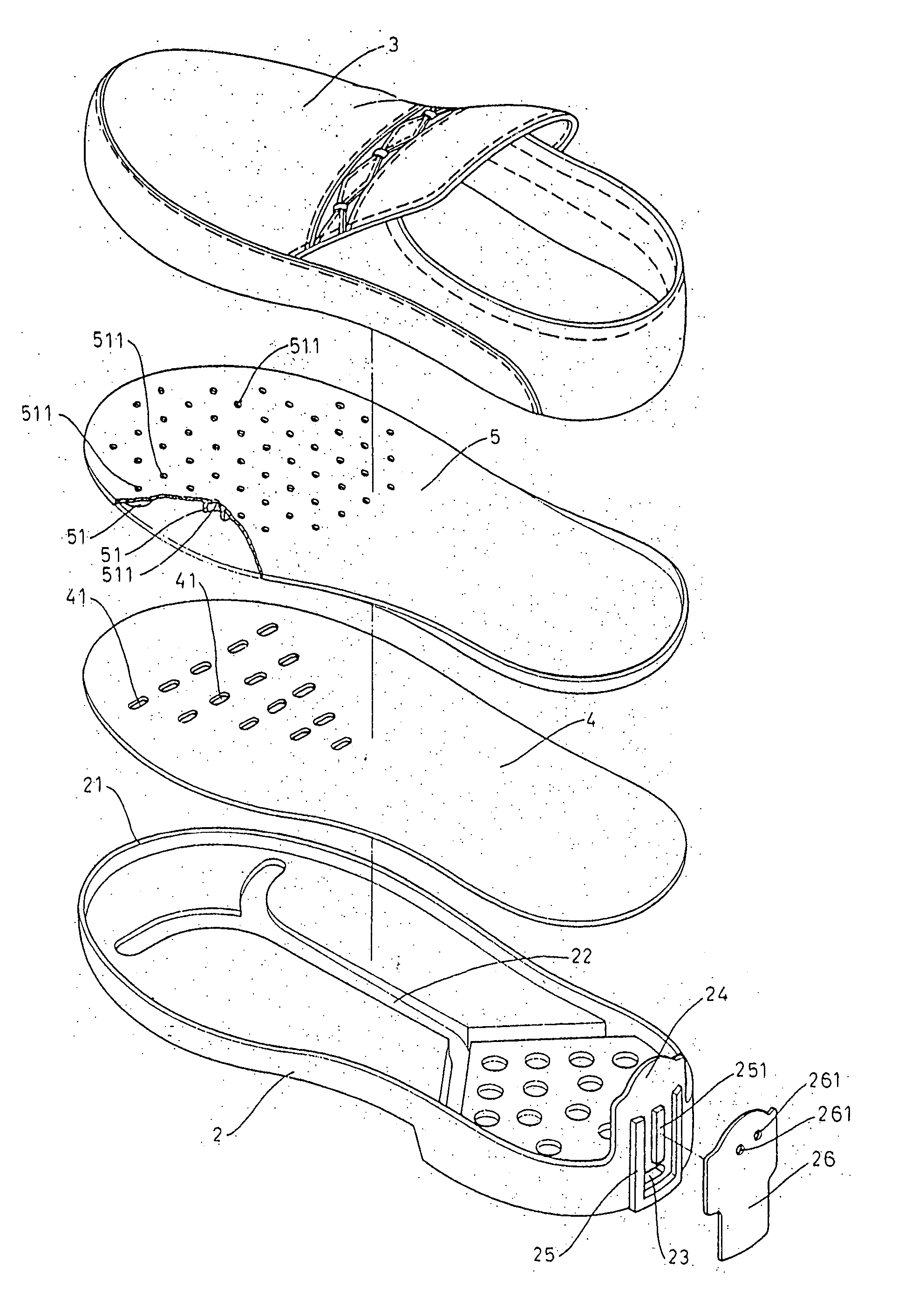
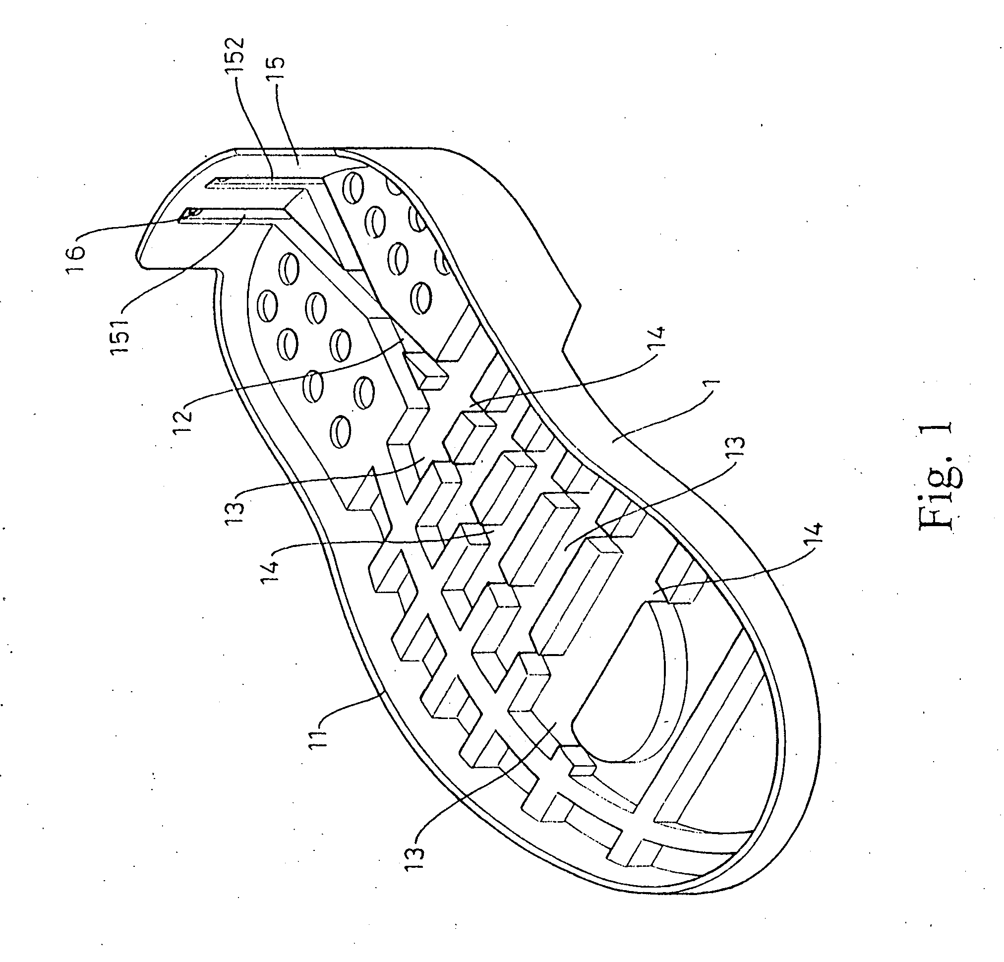
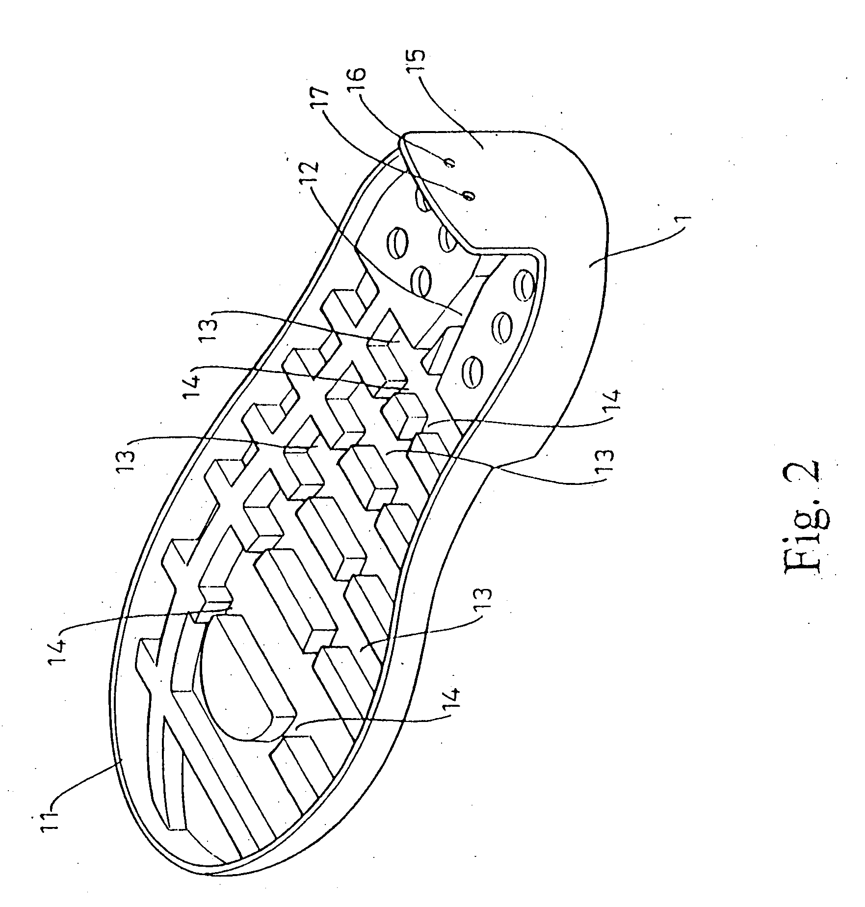
[0019] Referring to FIGS. 1 and 2, the shoe sole 1 of the present invention is bounded by a short wall portion 11 for attaching a shoe body. The upper surface of the heel portion of the shoe sole 1 is provided with an X-shaped groove 12. The upper surface of the palm and arch portions of the shoe sole 1 are provided with a plurality of transverse recesses 13 for passing air. The structures within the shoe sole 1 are integrally formed with the shoe sole 1. The transverse recesses 13 are crossed by a couple of main passages 14 extending from one end of the X-shaped groove 12. Thereby, when a top is placed on the shoe sole 1, the X-shaped groove 12 , the transverse recesses 13 and the main passages 14 form a plurality of connected passages for ventilating air.
[0020] Referring to FIG. 3, a flange 15 extends from the rear side of the shoe sole 1. The inner wall of the flange 15 is provided with two vertically elongated air chambers 151, 152 for air passage. The top ends of the air chambers 151, 152 are terminated just below the top edge of the flange 15, and the bottom ends of the air chambers 151, 152 are connected to the rear end of the X-shaped groove 12. Therefore, the air chambers 151, 152 are connected to the air passages on the upper surface of the shoe sole 1, forming two L-shaped air-ventilating structures. The upper ends of the air chambers 151, 152 are respectively provided with vent holes 16, 17, which pass through the flange 15 for exchanging cool air outside with the warm and humid air inside.
[0021] After a shoe body is attached to the shoe sole 1, the openings of the air chambers 151, 152 of the shoe sole 1 are covered by the rear surface of the shoe body, thereby forming two air passages. When the person wearing a pair of shoes equipped with shoe soles of this kind is walking, periodically exerted pressure above the shoe soles drives airflow through the vent holes 16, 17. The outside air entering the air chambers 151, 152 continue to pass through the netted air passages composed of the X-shaped groove 12, the recesses 13 and the main passages 14 so as to mix with the warm, humid air inside the shoe sole 1. The mixed air having excessive pressure therefore goes through the netted air passages, the air chambers 151, 152 and the vent holes 16, 17, leaving the shoe sole 1. Since the vent holes 16, 17 are disposed near the upper end of flange 15 of the shoe sole 1, wearing a pair of shoes having the air-ventilating shoe soles in rain or in a shallow water pit will not cause water permeation problem.
[0022] The air-ventilating structure of the shoe sole 1 is integrally formed with the shoe sole 1, which not only lowers the production cost but also prevents affecting the outlook and the comfort of the shoe the shoe sole I attached to.
[0023] Referring to FIG. 4, the second preferred embodiment of the present invention has the single the air chamber 151 on the inner surface of the flange 15. The bottom end of the air chamber 151 is connected to one branch of the rear end of the X-shaped groove 12. Thought slightly different in the netted structure, this preferred embodiment has exactly the same function as the first preferred embodiment.
[0024] Referring to FIGS. 5 and 6, another preferred embodiment of the present invention wherein the connectivity of the netted air passages is different. The heel portion of the shoe sole 1 is provided with two substantially parallel grooves 12′, respectively connected to the bottom ends of the air chambers 151, 152. The front ends of the parallel groove 12′ are connected to two main passages 14′ in the front portion of the shoe sole 1. Thought slightly different in the netted structure, this preferred embodiment has exactly the same function as the first preferred embodiment.
[0025] Referring to FIGS. 7 and 8, the fourth preferred embodiment of the present invention has a pair of flanges 1′0 respectively extending from two lateral sides of the shoe sole 1′, corresponding to the arch portion of the feet. Each of the flanges 1′0 is provided with two the air chambers 1′01, 1′02. The air chambers 1′01, 1′02 are respectively provided with vent holes 10′3, 10′4, which go through the top portions of flanges 1′0. The bottom ends of the air chambers 1′01, 1′02 are connected two an Ω-shaped or an λ-shaped air passages 1′8 or 1′9, as shown respectively in FIGS. 7 and 8. Thereby, the cool air outside can flows through the vent holes 10′3, 10′4 into the air chambers 1′01, 1′02 and then into air passages 1′8 or 1′9 for mixing with warm, humid air inside to achieve an air-ventilating effect. The air-ventilating structure of this preferred embodiment is also integrally formed with the shoe sole 1′, which not only lowers the production cost but also prevents affecting the outlook and the comfort of the shoe the shoe sole 1′ attached to.
[0026] Referring to FIGS. 9 and 10, the fifth preferred embodiment of the present invention provides a shoe sole 2 bounded by a short wall section 21 for attaching a shoe body 3. A top pad 4 having a plurality of through holes 41 is placed on the shoe sole 2 so that it is connected to the air passages 22 within the shoe sole 2. a shoe pad 5 provided with a multitude of circular granules 51. A plurality of through holes 511 are distributed among the circular granules 51 for passing air through the through holes 41 on the top pad 4 to the air passages 22 within the shoe sole 2. Thereby, this preferred embodiment provides a very effective air-ventilating structure within a shoe.
[0027] Referring to FIG. 11, a double-Y-shaped air passage 22 is formed on the top surface of a shoe sole 2. A ventilating channel 23 is formed within the heel portion, with a front end connecting the double-Y-shaped air passage 22. A rear end of the ventilating channel 23 extends out of the heel portion of the shoe sole 2, thereby air flowing through the double-Y-shaped air passage 22 and the ventilating channel 23 freely. A flange 24, which is bulged at the center of the top edge thereof, extends from the rear end of the shoe sole 2. The outer face of the flange 24 is provided with a U-shaped frame 25 that encloses the rear exit of the ventilating channel 23 so that the airflow through the ventilating channel 23 can be confined and guided upward. The bottom edge of the U-shaped frame 25 is aligned with the bottom edge of the heel portion of the shoe sole 2. The area enclosed by the U-shaped frame 25 is further divided into a right and a left air passages by a vertically disposed partition strip 251.
[0028] A cover 26 is for covering the U-shaped frame 25 on the flange 24. The boundary of the lower portion of the U-shaped frame 25 is aligned with the U-shaped frame 25. The upper portion takes the same shape as the corresponding part of the flange 24. The lower portion of the cover 26 is connected to the shoe sole 2 by glue, whereas the upper portion of the cover 26 is connected to the shoe body and the flange 24 by sewing. The rear exit of the ventilating channel 23 thereby is isolated from outside. The U-shaped frame 25 and the partition strip 251, sandwiched by the flange 24 and cover 26, provide upward air passages leading to the rear exit of the ventilating channel 23. The upper end of the cover 26 is provided with a pair of vent holes 261, each for an air passage defined by the U-shaped frame 25 and the partition strip 251. The air passages within the shoe sole 2 and those extending upwardly in the rear flange 24 form an L-shaped air-ventilating structure by which the ambient air and the air inside the shoe sole 2 are exchanged.
[0029] As shown in FIG. 12, in another preferred embodiment, the outer face of the rear flange 24′ is provided with a flow guiding part 25′. The left and the right edges of the flow guiding part 25′ is each provided with a slot 25′2. The right and the left slots 25′2 retain two lateral sides of a cover 26′ so that the cover 26′ is secured by the rear flange 24′, leaving a room therebetween for passing air. A partition strip 25′1 is disposed on the flow guiding part 25′ so that the room for passing air is divided into a left and a right air passages. Thus this preferred embodiment provides exactly the same air-ventilating function as the previous preferred embodiment.
[0030] Further, the air passage 22′ formed on the top surface of a shoe sole 2 can be triangular or of other shapes. The ventilating channel 23′ can be an indentation formed in the heel portion of the shoe sole 2. The present invention is thus described, and it will be obvious that the same may be varied in many ways. Such variations are not to be regarded as a departure from the spirit and scope of the present invention, and all such modifications as would be obvious to one skilled in the art are intended to be included within the scope of the following claims.

PUM

no PUM

Description & Claims & Application Information

We can also present the details of the Description, Claims and Application information to help users get a comprehensive understanding of the technical details of the patent, such as background art, summary of invention, brief description of drawings, description of embodiments, and other original content. On the other hand, users can also determine the specific scope of protection of the technology through the list of claims; as well as understand the changes in the life cycle of the technology with the presentation of the patent timeline. Login to view more.

Similar technology patents

Wafer processing method

ActiveUS20200286784A1prevent problem
Owner:DISCO CORP

Device and method for detection and treatment of bruxism

ActiveUS11298073B1prevent habituationprevent problem
Owner:DELTA NEURO INC

Locking water ski and boating equipment storage rack

InactiveUS20060070567A1prevent problemsimple mechanism
Owner:MIDDLETON PAUL LAWRENCE

Classification and recommendation of technical efficacy words

  • prevent problem

Liquid crystal display apparatus

InactiveUS7233304B1prevent problem
Owner:PANASONIC LIQUID CRYSTAL DISPLAY CO LTD +1

Magnetic head for perpendicular magnetic recording and method of manufacturing same

ActiveUS20080316653A1prevent problemimprove write characteristic
Owner:HEADWAY TECH INC

DC-DC converter

InactiveUS7113379B2prevent problemsimple circuit configuration
Owner:MURATA MFG CO LTD

Sheet-supply device

ActiveUS7000916B2prevent problem
Owner:BROTHER KOGYO KK
Why Eureka
Try Eureka