Leakage detecting apparatus for an exhaust gas re-circulating system of an engine

a technology of leakage detection and exhaust gas, which is applied in the direction of fluid tightness measurement, electrical control, instruments, etc., can solve the problems of bad emissions after passing through the catalyst and the inability of the machine to detect leakage failures

Inactive Publication Date: 2005-07-28
HONDA MOTOR CO LTD
View PDF8 Cites 29 Cited by
  • Summary
  • Abstract
  • Description
  • Claims
  • Application Information

AI Technical Summary

Benefits of technology

[0006] In order to resolve the above-described problem, the present invention provides an apparatus for detecting a leakage of a re-circulating passage. The apparatus has a re-circulating passage for re-circulating an exhaust gas from an exhaust system to an air intake system in an engine, a re-circulating valve that is disposed in the re-circulating passage to control a flow rate of the re-circulating exhaust gas, operation amount detecting means for detecting an operation amount of the re-circulating valve and an A / F ratio sensor for detecting an A / F ratio of the exhaust system. The apparatus further includes means for calculating a correlation between outputs of the operation amount detecting means and outputs of the A / F ratio sensor so as determine a leakage in the re-circulating passage based on the calculated correlation.

Problems solved by technology

However, this conventional technique cannot detect such leakage failure wherein the outside air flows into the recirculation passage due to occurrence of a crack or a disconnection in the recirculation passage.
As a result, the emission after passing through the catalyst becomes bad.

Method used


Image

  • Leakage detecting apparatus for an exhaust gas re-circulating system of an engine
  • Leakage detecting apparatus for an exhaust gas re-circulating system of an engine
  • Leakage detecting apparatus for an exhaust gas re-circulating system of an engine

Examples


Embodiment Construction

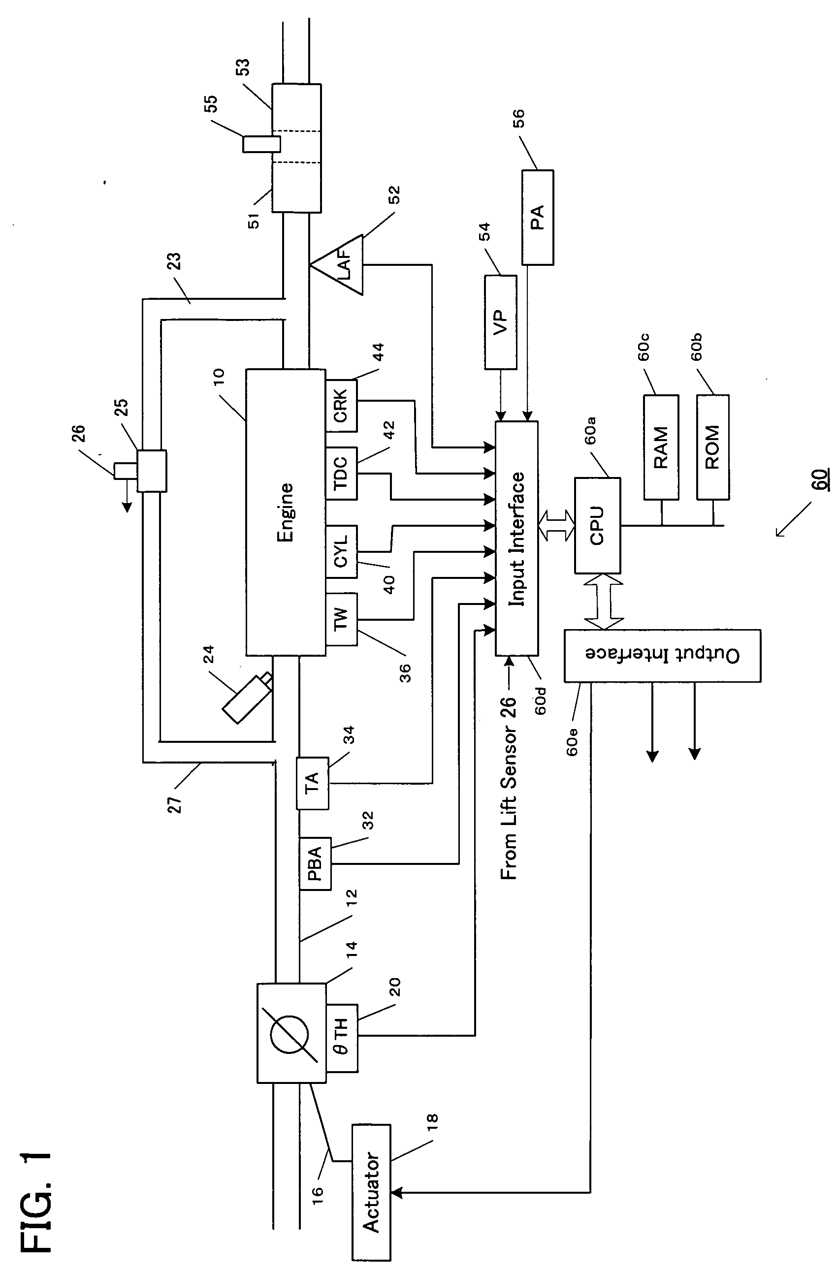
[0015] An embodiment of the present invention will be now described with reference to the accompanying drawings. FIG. 1 is a block diagram showing an overall structure of an idle rotational speed control unit for an engine. An engine 10 is, for example, a 4-cylinder automobile engine. A throttle valve 14, which is a main throttle valve, is disposed in an air intake pipe 12. The throttle valve 14 is driven by an actuator 18 in accordance with a control signal from an electronic control unit (ECU) 60. In accordance with a detected output from a depression amount sensor for an accelerator pedal (not shown), the ECU 60 sends a control signal for controlling an opening / closing of the throttle valve 14 to the actuator 18. This control is called a drive-by-wire scheme. As another scheme, there is a technique for controlling a throttle valve directly by an accelerator pedal that is connected to a wire 16. A throttle valve opening sensor 20 is disposed near the throttle valve 14 in order to ...


PUM


Abstract

A leakage detecting apparatus includes a re-circulating passage for re-circulating an exhaust gas from an exhaust system to an air intake system in the engine, a re-circulating valve disposed in the re-circulating passage to control a flow rate of the re-circulating exhaust gas, and an A/F ratio sensor for detecting an A/F ratio of the exhaust system. An electronic control unit detects an operation amount of the re-circulating valve and calculates correlation between the operation amount and output of the A/F ratio sensor to determine a leakage in the re-circulating passage. The correlation is obtained by an inner product calculation of a vector of deviations of a time-sequence vector of the operation amount relative to a moving average and a vector of deviations of a time-sequence vector of the output of the A/F ratio sensor relative to a moving average. Leakage in the re-circulating passage is detected when an accumulated value of the inner product values over a predetermined period exceeds a threshold value.

Description

BACKGROUND OF THE INVENTION [0001] The present invention relates to a failure detection for an internal-combustion engine in which exhaust gas recirculation is applied. [0002] Conventionally, an intake air amount into an engine is controlled by returning a part of the exhaust gas to the intake air (this approach is referred to as “exhaust gas recirculation (EGR)”). Since the oxygen density in the intake air decreases when the EGR is applied, a combustion temperature becomes lower, contributing to reduction of the generated NOx emission. [0003] Japanese Patent No. 3097491 discloses a technique for detecting a clogging in a recirculation passage in an engine having an EGR mechanism based on a relation between an engine operating condition and a significance of a pulsation of an output from a pressure sensor disposed in the recirculation passage. [0004] However, this conventional technique cannot detect such leakage failure wherein the outside air flows into the recirculation passage d...

Claims


Application Information

Patent Timeline
Patent Type & Authority Applications(United States)
IPC IPC(8): F02D21/08F02D41/00F02D41/02F02D41/14F02D41/22F02D45/00F02M25/07G01M3/02
CPCF02D41/0065F02D41/1454F02D41/1456Y02T10/47F02M25/0756G01M3/025F02M25/0702F02M26/48F02M26/49Y02T10/40
Inventor ISHIKAWA, YOSUKE
Owner HONDA MOTOR CO LTD
Why Eureka
Try Eureka