Fluid dispenser calibration system and method

a calibration system and dispenser technology, applied in the field of fluid delivery systems, can solve the problems of labor-intensive and tedious calibration process

Active Publication Date: 2005-07-28
TAYLOR COMML FOODSERVICE LLC
View PDF12 Cites 13 Cited by
  • Summary
  • Abstract
  • Description
  • Claims
  • Application Information

AI Technical Summary

Benefits of technology

[0009] The function used for calibration allows calibration to occur automatically by converging system operation to the ideal dispensing characteristic, without requiring a user to calibrate the system through manual iterative methods.

Problems solved by technology

Because current systems require manually iterative adjustments to obtain the desired fluid volume in each unit, calibration tends to be a tedious, labor-intensive process.

Method used


Image

  • Fluid dispenser calibration system and method
  • Fluid dispenser calibration system and method
  • Fluid dispenser calibration system and method

Examples


Embodiment Construction

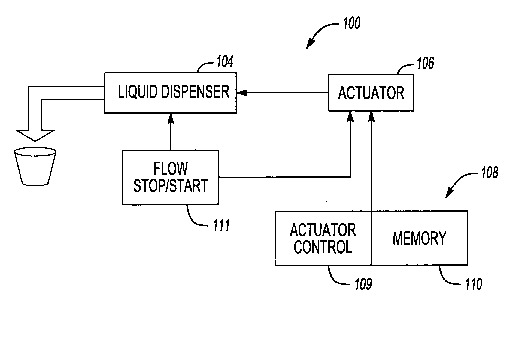
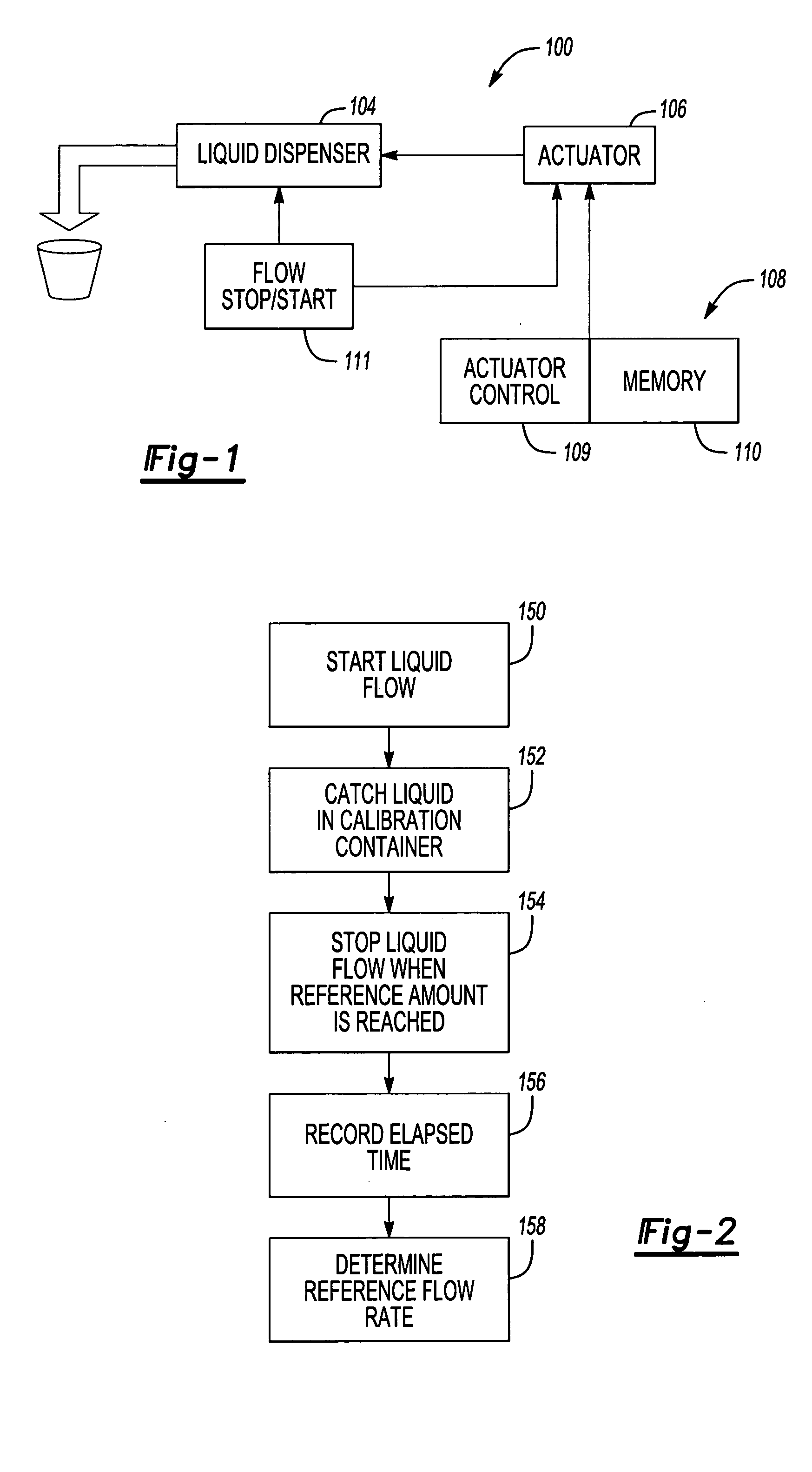
[0019]FIG. 1 is a representative diagram illustrating components of a fluid dispensing system 100 according to one embodiment of the invention. The system 100 includes a fluid dispenser 104 (e.g., a peristaltic pump), a motor 106 or other actuator to operate the fluid dispenser 104, and a controller 108 that allows control of the motor's 106 speed. The controller 108 can be any known processor, actuator control, and / or motor control device that can adjust motor or actuator speed via a generated control signal, such as a pulse width modulated signal, a variable voltage signal, etc. Changes in the motor speed will change the operation speed of the dispenser 108.

[0020] In one embodiment, the controller 108 includes an actuator control 109 and a memory 110 that is able to store data on fluid dispensing times and corresponding motor speeds and / or dispensing speeds as well as functions or algorithms linking dispensing speeds, times and volumes. Note that the memory 110 does not necessari...


PUM


Abstract

A system and method for calibrating fluid detects an actual fluid dispensing characteristic, such as dispensing speed, and automatically adjusts the dispensing characteristic to match an ideal dispensing characteristic. The adjustment is conducted by a controller that controls fluid dispensing based on a function that correlates dispensing speed, a dispensed volume, and a dispensing time. The function allows calibration to occur automatically by converging system operation to the ideal dispensing characteristic, without requiring a user to calibrate the system through manual iterative methods.

Description

REFERENCE TO RELATED APPLICATION [0001] This application is a continuation-in-part of co-pending U.S. patent application Ser. No. 10 / 296,186 filed on Nov. 21, 2002.TECHNICAL FIELD [0002] The present invention relates to fluid delivery systems, and more particularly to a system that can be calibrated to dispense a pre-determined volume of fluid. BACKGROUND OF THE INVENTION [0003] Many applications require fluid delivery systems that can dispense units of fluid having a pre-determined volume. Fluid delivery systems often use a motor speed to control the volume of fluid dispensed at one time. For example, a peristaltic fluid delivery system includes a rotating roller that squeezes flexible tubing at selected intervals, thereby pushing generally equal units of fluid along the tubing for output. The motor controls the roller's rotation speed, thereby controlling the volume of fluid dispensed as the roller squeezes the flexible tube; the faster the motor speed, the greater the volume of f...

Claims


Application Information

Patent Timeline
Patent Type & Authority Applications(United States)
IPC IPC(8): G01F25/00B67D7/08
CPCB67D1/0006B67D1/0012B67D1/0032G01F25/0092B67D1/1231G01F25/0038B67D1/12G01F25/17B67D7/08
Inventor ROADY, ROGERSCORDATO, JOSEPH JOHN
Owner TAYLOR COMML FOODSERVICE LLC
Why Eureka
Try Eureka