Wireless transmitting and receiving device and method

a wireless receiving device and wireless technology, applied in the field of wireless transmitting devices and wireless receiving devices, can solve the problems of degrading the receiving performance, adversely affecting the processing after a/d conversion, and severe quantization errors in the output so as to reduce the number of resolution bits of the a/d converter, short time, and enhance the receiving performance of the wireless receiving devi

Active Publication Date: 2005-07-28
PALMIRA WIRELESS AG
View PDF7 Cites 54 Cited by
  • Summary
  • Abstract
  • Description
  • Claims
  • Application Information

AI Technical Summary

Benefits of technology

[0013] Since a signal format employed in the invention includes preambles for fine tune the AGC for MIMO reception transmitted from multiple antennas, the input level of an A / D converter can be appropriately adjusted with a short time, thereby enhancing the receiving performance of a wireless receiving device and reducing the number of resolution bits of the A / D converter.

Problems solved by technology

On the other hand, when the receiving level is lower than the lower limit of the input dynamic range of the A / D converter, the output of the A / D converter suffers a severe quantization error.
In either case, the A / D converter cannot perform appropriate conversion, which adversely influences the processing after A / D conversion.
Therefore, during data transmission, the range of variations in receiving level is further increased, which worsens the above-mentioned saturation of the A / D converter output and / or the quantization error therein, thereby significantly degrading the receiving performance.
As described above, in the Boer's proposed preamble, AGC is performed at the receive side using only the short-preamble sequence transmitted from a single transmit antenna, which makes it difficult to deal with variations in receiving level that may occur when signals transmitted from the other antennas in MIMO mode are received.

Method used


Image

  • Wireless transmitting and receiving device and method
  • Wireless transmitting and receiving device and method
  • Wireless transmitting and receiving device and method

Examples


Embodiment Construction

[0030] Embodiments of the invention will be described in detail with reference to the accompanying drawings.

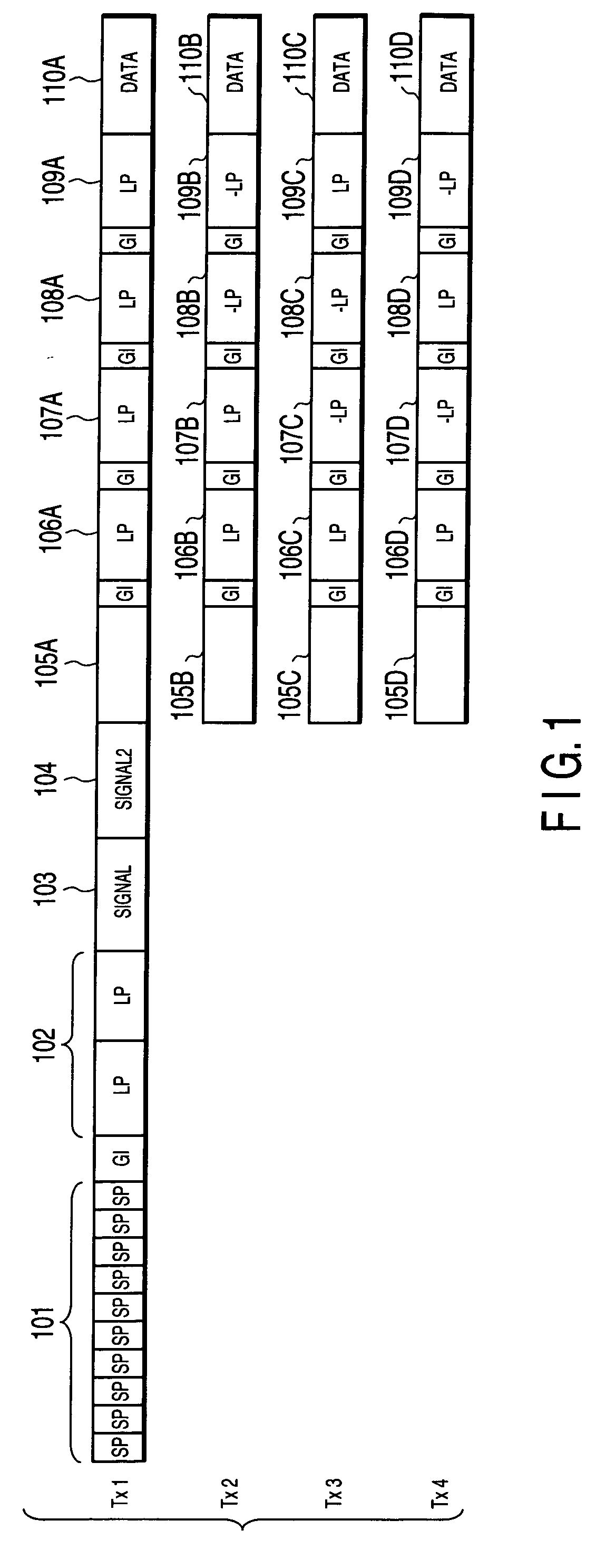
[0031]FIG. 1 shows a format for a wireless packet employed in a first embodiment of the invention. This format is a physical layer protocol data unit format for the MIMO mode and provides interoperability and coexistence with IEEE802.11a wireless stations.

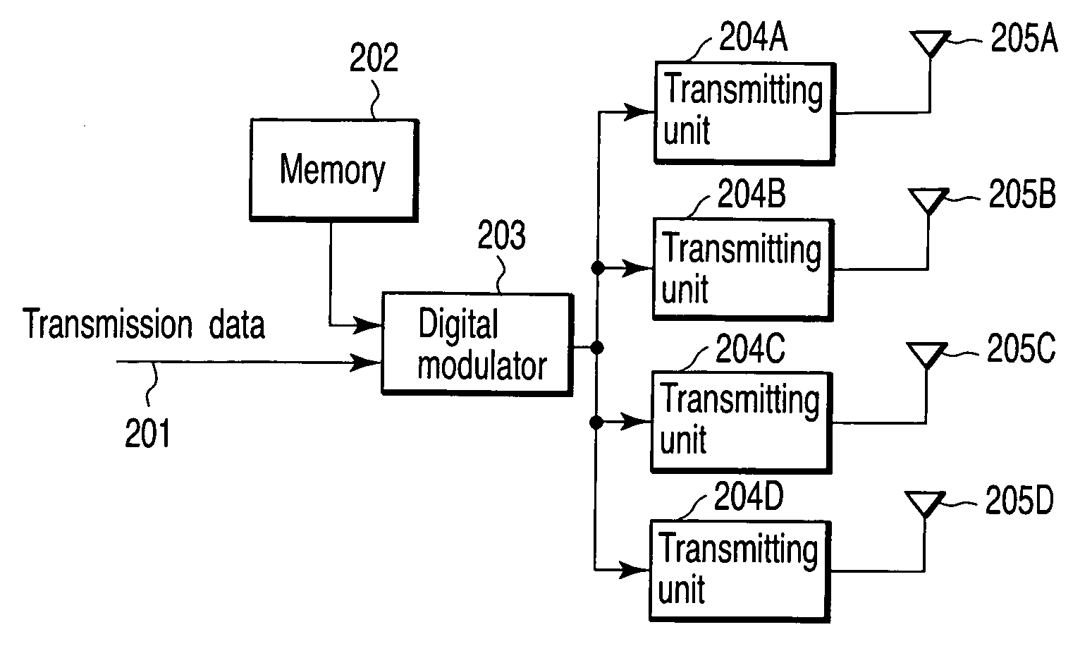
[0032] As seen from FIG. 1, a preamble includes a physical layer convergence protocol (PLCP) signal transmitted from an antenna Tx1. The PLCP signal includes a short-preamble sequence 101, first long-preamble sequence 102, first signal field (SIGNAL) 103 and second signal field (SIGNAL 2) 104. The short-preamble sequence 101 contains several unit preambles SP. The long-preamble sequence 102 contains the unit preambles LP having respective predetermined lengths. The preambles LP are longer than the preambles SP.

[0033] The short-preamble sequence 101, first long-preamble sequence 102 and first signal field 103 conform to IEE...


PUM


Abstract

A wireless device, method, and signal for use in communication of a wireless packet between transmitting device and a wireless receiving device via a plurality of antennas, wherein a signal generator generates wireless packet including a short-preamble sequence used for a first automatic gain control (AGC), a first long-preamble sequence, a signal field used for conveying a length of the wireless packet, an AGC preamble sequence used for a second AGC to be performed after the first AGC, a second long-preamble sequence, and a data field conveying data. The AGC preamble sequence is transmitted in parallel by the plurality of antennas.

Description

CROSS-REFERENCE TO RELATED APPLICATIONS [0001] This application is based upon and claims the benefit of priority from prior Japanese Patent Applications No. 2003-433347, filed Dec. 26, 2003; and No. 2004-357097, filed Dec. 9, 2004, the entire contents of both of which are incorporated herein by reference. BACKGROUND OF THE INVENTION [0002] 1. Field of the Invention [0003] The present invention relates to a wireless transmitting device and wireless receiving device for respectively transmitting and receiving radio signals in mobile communication system like a wireless LAN, using a wireless packet including a preamble and data, and a wireless transmission method and wireless receiving method for use in the devices. [0004] 2. Description of the Related Art [0005] The Institute of Electrical and Electronics Engineers (IEEE) is now defining a wireless LAN standard called IEEE 802.11n, which aims to achieve a high throughput of 100 Mbps or more. It is very possible that IEEE 802.11n will ...

Claims


Application Information

Patent Timeline
Patent Type & Authority Applications(United States)
IPC IPC(8): H04J99/00H03G3/30H04B7/005H04J11/00H04L25/02
CPCH03G3/3052H04L25/0226H04B7/04H04W52/52H04W84/12
Inventor AOKI, TSUGUHIDETAKEDA, DAISUKEKOBAYASHI, TAKAHIROTANABE, YASUHIKO
Owner PALMIRA WIRELESS AG
Why Eureka
Try Eureka