
Slide mechanism

a slide and mechanism technology, applied in mechanical devices, electrical apparatus construction details, casings/cabinets/drawers, etc., can solve the problems of high production cost and complex structure of slide cases, and achieve the effect of reducing cost, simple structure and reducing number of parts

Inactive Publication Date: 2005-07-28
KATOH ELECTRIC MACHINERY
View PDF6 Cites 35 Cited by
  • Summary
  • Abstract
  • Description
  • Claims
  • Application Information

AI Technical Summary

Benefits of technology

[0007] In view of the above, it is an object of the present invention to provide a slide mechanism of a portable terminal device which, having a minimal number of parts and keeping the same function as that of a conventional one, enables a substantial production cost reduction.
[0008] In order to achieve the object stated above, the present invention is a mechanism for relatively sliding a first casing and a second casing in a state that the casings are laid over each other in a vertical direction, and is constituted with: a slide case mounted on either one of the first casing and the second casing; a slider slidably accommodated in the slide case and mounted on the other one of the first casing and the second casing; and a resilient means resiliently disposed between the slider and the slide case. Additionally, the present invention is characterized in that the slide case is formed as an integral structure with a guide groove which extends to both ends in a longitudinal direction with the one end thereof being opened, that the slider has a shape which enables the slider to be inserted into the guide groove in an engaged state from the open end side, and that the slide case is further provided with a stopper portion preventing the slider from coming off after the slider is inserted into the guide groove.
[0009] Further, the present invention is the mechanism for relatively sliding the first casing and the second casing in the state that the casings are laid over each other in the vertical direction, and is constituted with: the slide case mounted on either one of the first casing and the second casing; the slider slidably accommodated in the slide case and mounted on the other one of the first casing and the second casing; and the resilient means resiliently disposed between the slider and the slide case. Additionally, the present invention is characterized in that the slide case is formed as the integral structure with the guide groove which extends to the both ends in the longitudinal direction with the one end thereof being opened, that the slider has a projecting shape in a cross section which enables the slider to be inserted into the guide groove in the engaged state from the open end side, and that the slide case further provided with the stopper portion preventing the slider from coming off after the slider is inserted into the guide groove.
[0011] The above-described invention can also be structured such that the resilient means is structured of one leaf spring with an arched shape and that the slider is provided with projection portions preventing a wobble of the slider at both sides across a top portion of the leaf spring.
[0015] Since the slide case is formed integrally and has a simple structure, a number of parts and a man-hour for assembly are reduced so that a substantial cost reduction is achievable. Additionally, by providing the sliding case with the stopper portion, the slider which is fit into the guide groove can be easily prevented from coming off. Further, by providing the slider with projection portions it becomes possible that only one leaf spring is required to be disposed between the slide case and the slider, and also in this respect, the number of parts is reduced to achieve the cost reduction.

Problems solved by technology

Consequently, the structure of the slide case becomes complex.
As a result, there exists a problem that a production cost becomes high.

Method used


Image

  • Slide mechanism
  • Slide mechanism
  • Slide mechanism

Examples


Embodiment Construction

[0030] Hereinafter, a case that an embodiment of the present invention is applied to a cellular phone will be described, but a slide mechanism according to the present invention can also be applied to a portable information terminal such as Zaurus (trademark) for example, a calculator, a pocket computer, a hand-held gaming device, an ashtray, a cover of a case and so forth.

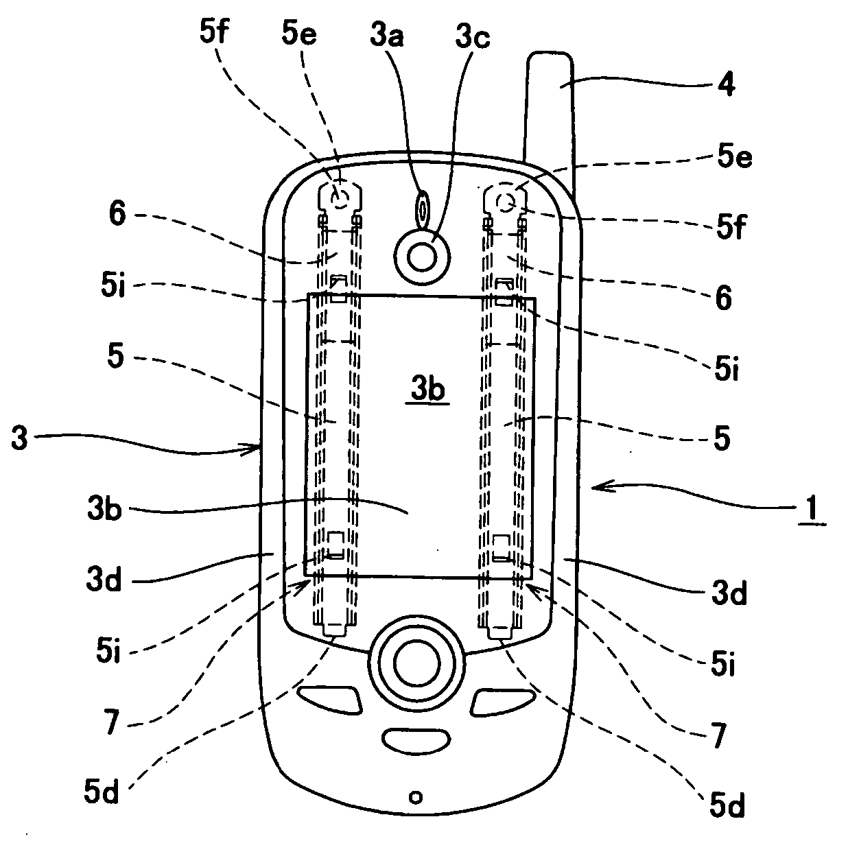
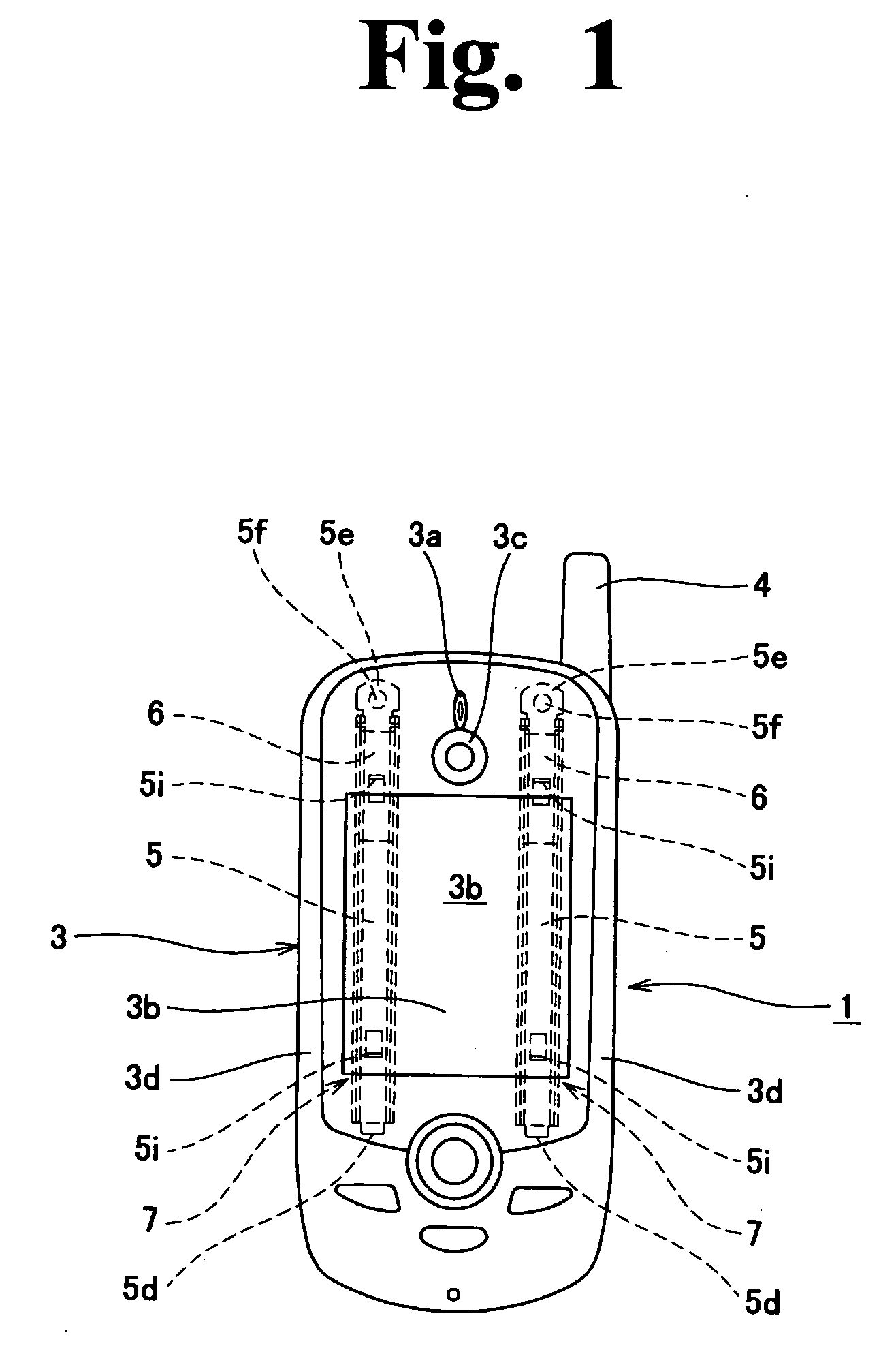
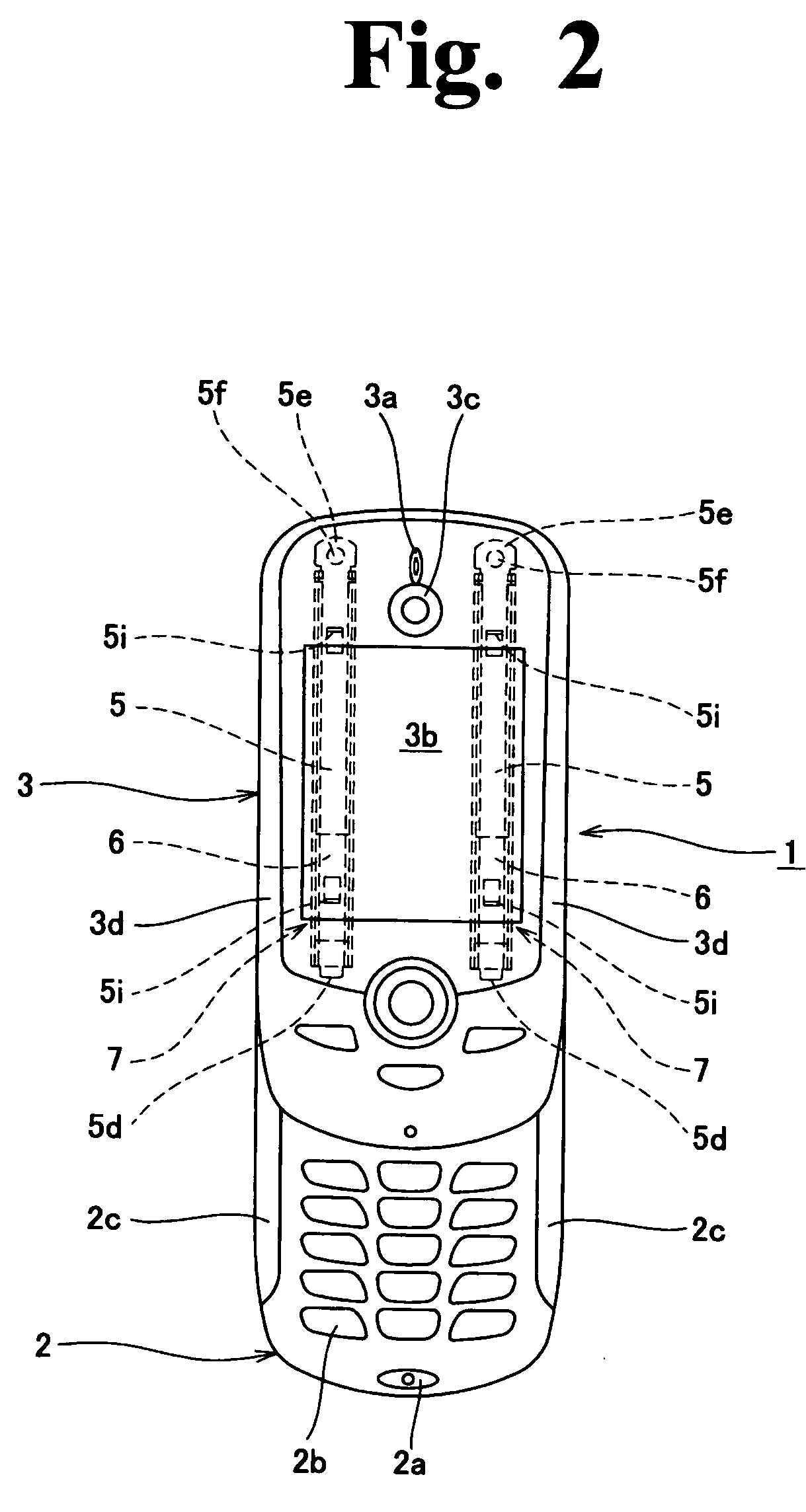
[0031] Hereinafter, the embodiment of the present invention will be described in detail based on FIG. 1 to FIG. 9. In FIG. 1 to FIG. 3 in particular, a reference numeral 2 denotes a transmitter section of the cellular phone 1 as one type of a portable terminal device, and this transmitter section constitutes a first casing. On a front surface of the first casing 2, a microphone portion 2a and a keyboard portion 2b are provided. Laid over an upper part of the first casing 2 and mounted slidably in a longitudinal direction by the slide mechanism according to the present invention is a receiver section of the cellul...


PUM


Abstract

To attain a slide mechanism of a portable terminal device which, having a minimal number of parts and keeping the same function as that of a conventional one, enables a substantial production cost reduction, a mechanism relatively slides a first casing and a second casing in a state that the casings are laid over each other in a vertical direction, and is constituted with: a slide case mounted on either one of the first casing and the second casing; a slider slidably accommodated in the slide case and mounted on the other one of the first casing and the second casing; and a resilient means resiliently disposed between the slider and the slide case. The slide case is formed as an integral structure with a guide groove which extends to both ends in a longitudinal direction with the one end thereof being opened. Additionally the slider has a shape which enables the slider to be inserted into the guide groove in an engaged state from the open end side. Also, the slide case is further provided with a stopper portion preventing the slider from coming off after the slider is inserted into the guide groove.

Description

BACKGROUND OF THE INVENTION [0001] 1. Field of the Invention [0002] The present invention relates to a slide mechanism of a portable terminal device, and this slide mechanism is suitably used when a first casing which constitutes a transmitter section and a second casing which constitutes a receiver section of the portable terminal device such as a cellular phone in particular are slidably coupled to each other. [0003] 2. Description of the Related Art [0004] Currently on the market is a cellular phone, as one type of a portable terminal device, which has a slide mechanism for making, in a state that a first casing being a transmitter section with a keyboard portion and a microphone portion and a second casing being a receiver section with a display portion and a speaker portion are laid over each other, a state that the first casing and the second casing are completely laid over each other with the second casing covering an upper surface of the first casing and a state that the sec...

Claims


Application Information

Patent Timeline
Patent Type & Authority Applications(United States)
IPC IPC(8): H04B1/38F16C29/02H04M1/00H04M1/02H05K5/02H05K7/00H05K7/14H05K7/18
CPCF16C29/02H04M2250/52H04M1/0237H04B1/38H04M1/02
Inventor NISHIHARA, TAICHI
Owner KATOH ELECTRIC MACHINERY
Learn More