Feedback control method and feedback control device
a control method and feedback technology, applied in the field of process control techniques, can solve the problems of inability to cope with operation, control is not suitable for a controlled system, and the control system does not have linearity, so as to achieve the effect of easy adjustment of parameters
- Summary
- Abstract
- Description
- Claims
- Application Information
AI Technical Summary
Benefits of technology
Problems solved by technology
Method used
Image
Examples
first embodiment
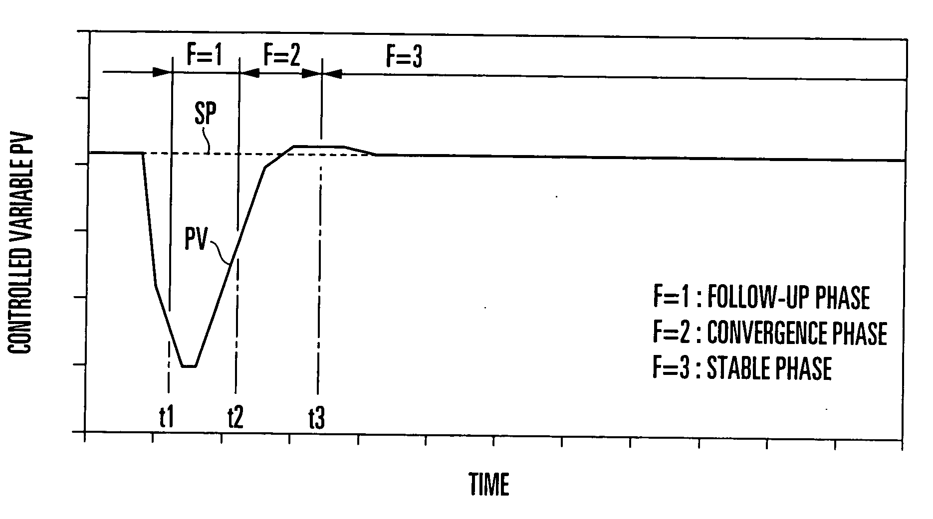
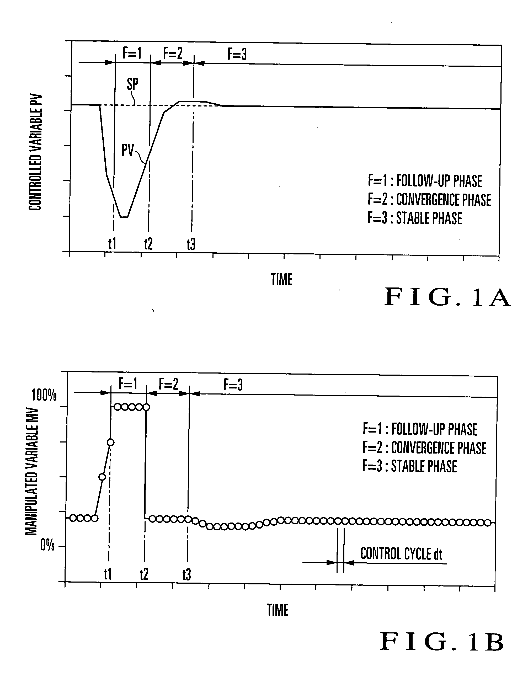
[0041] The first embodiment of the present invention will be described in detail below with reference to the accompanying drawings. In this embodiment, the response process of disturbance recovery control accompanying the application of a disturbance is divided into three stages of phases (a follow-up phase, a convergence phase, and a stable phase). A proper, simple manipulated variable output sequence is assigned to each phase, and a series of phases are combined to forcibly and directly shape the response waveform of disturbance recovery control.
[0042]FIGS. 1A and 1B are waveform charts for explaining a follow-up phase, convergence phase, and stable phase in this embodiment. FIG. 1A is a chart showing changes in controlled variable PV (response waveform). FIG. 1B is a chart showing changes in manipulated variable MV. The symbol “◯” in FIG. 1B indicates the manipulated variable MV output in each control cycle dt.
[0043] First of all, in a response process, the interval from a time...
second embodiment
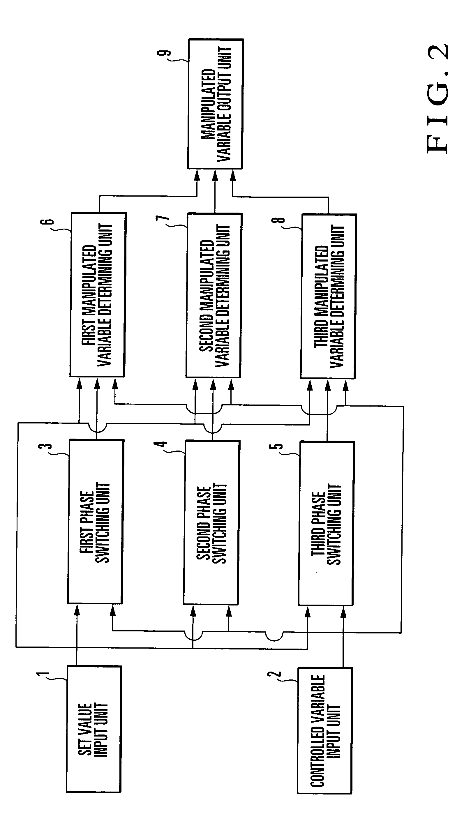
[0090] The second embodiment of the present invention will be described next. This embodiment shows another example in which the present invention is applied to fast disturbance recovery control. In this embodiment, the arrangement of a feedback control device and the flow of processing are the same as those shown in FIGS. 2 and 3, and hence will be described by using reference numerals in FIGS. 2 and 3. FIGS. 12A and 12B are waveform charts showing the operation of the feedback control device according to this embodiment. FIG. 12A is a chart showing changes in controlled variable PV. FIG. 12B is a chart showing changes in manipulated variable MV. The symbol “◯” in FIG. 12B indicates the manipulated variable MV output in each control cycle dt.
[0091] In this embodiment, assume that a switching time point (disturbance application detection time point) t1 from a stable phase to a follow-up phase is a time point at which a deviation Er between a set point SP and a controlled variable P...
third embodiment
[0103] The third embodiment of the present invention will be described next. This embodiment shows another example in which the present invention is applied to fast disturbance recovery control. In this embodiment, the arrangement of a feedback control device and the flow of processing are the same as those shown in FIGS. 2 and 3, and hence will be described by using reference numerals in FIGS. 2 and 3. FIGS. 13A and 13B are waveform charts showing the operation of a feedback control device according to this embodiment. FIG. 13A is a chart showing changes in controlled variable PV. FIG. 13B is a chart showing changes in manipulated variable MV. The symbol “◯” in FIG. 13B indicates the manipulated variable MV output in each control cycle dt.
[0104] In this embodiment, assume that a switching time point (disturbance application detection time point) t1 from a stable phase to a follow-up phase is a time point at which a phase switching signal is input from an external device which noti...
PUM
 Abstract
Description
Claims
Application Information
 - R&D
- Intellectual Property
- Life Sciences
- Materials
- Tech Scout
- Unparalleled Data Quality
- Higher Quality Content
- 60% Fewer Hallucinations
Browse by: Latest US Patents, China's latest patents, Technical Efficacy Thesaurus, Application Domain, Technology Topic, Popular Technical Reports.
© 2025 PatSnap. All rights reserved.Legal|Privacy policy|Modern Slavery Act Transparency Statement|Sitemap|About US| Contact US: help@patsnap.com


